Emergency Generator Solas requirements, starting and running Procedures

Emergency Generator Is A Source Of Electrical Powe

Emergency Generator Is A Source Of Electrical Power Which Supply Power To All Those Essential Services Required For The Ship's Safety And Navigation In Emergency Condition Like Loss Of Main Power Supply.

Q.1 What Are The Main Requirements Of Solas For Emergency Generator?
I) It Be Driven By Aprime Mover Which Consumes Fuel Having Flash Point Not Less Than 43 Deg C.
II) It Should Start And Connect Automatically To Main Switch Board (MSB) In Case Of Main Power Failure In Not More Than 45 Sec.

Q2. What Checks Is To Be Done Before Starting EG?
Checks Before Starting

A) Check Oil Level In The Engine Crankcase Is Normal.
B) Check Oil Level In The Diesel Oil Tank And Ensure That The Tank Outlet Valve To The Engine Is Open.
C) Check That The Air Supply Flaps Are Open.
D) Check That The Battery Selection Switch Is On 'Battery 1' Or 'Battery 2'.
E) Check The Belt Tension For The Cooling Air Fan.

Q3. Explain The Starting Procedure Of Emergency Generator?
The Emergency Generator Is Always Kept In A Stand By Mode (auto). When A Black Out Takes Place Due To Some Reason And The Stand By Main Generators Could Not Come On Load The Emergency Generator Will Start Automatically At Its Set Time And The Breaker Will Come On And Supply The Emergency Power To The Concern Places.
         The Emergency Generator Are Tried Out Weekly For Their Normal Working Operations It Can Be Started By Two Means One By Battery Start And Other By Hydraulic Start. The Black Out Test Is Carried Once In 3 Months.  
Procedures For Starting Emergency Generator

Starting On Manual Mode
A) Change Over The Manual / Auto Switch To Manual. 
B) Press The 'Start' Button, And The Engine Starts

Starting On Auto
A) Ensure That The Manual / Auto Switch Is On Auto.
B) Turn The Normal / Test Key To Test Position. A Black Out Signal Is Initiated To The Emergency Switch Board.
C) The Emergency Generator Starts And Comes On Load.

Q4. What Should Be Checked During Running Operations Of EG?
Checks During Running
A) Check The Lube Oil Pressure For The Engine Is Normal.
B) Check That The Cylinder Head Temperature Is Within Limits.
C) Check For Any Abnormal Noise / Vibrations At The Engine / Alternator.
D) Check For Fuel / Lube Oil Leaks.
E) Check For Normal Voltage And Frequency.

Q5. How To Stop Emergency G/E & What Are The Post Stopping Checks?
A) Press The Stop Push Button On The Control Panel – The Engine Will Stop.
B) Change Over The Selector Switch Back To AUTO.

After The Generator Has Stopped Check The Battery Condition Check The Specific Gravity, Check The Charging Current Of The Battery Whether It Is Charging At Normal Current, And Check The Water Level. On Board Battery Maintenance Are Carried Out Weekly.

Safety System for Switch Board and Generators

Apart From Direct Temperature Measurement Of The S

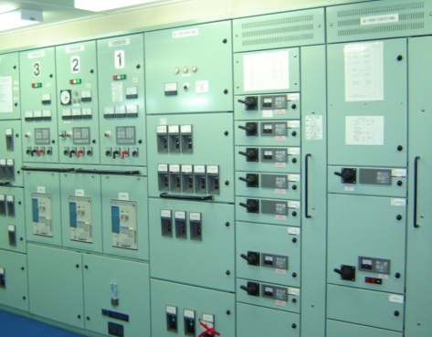
Apart From Direct Temperature Measurement Of The Stator Windings And The Internal Air, The Protection Of A Generator Is Largely Based On The Sensing Of Current And Voltage From Current Transformers (CT) And Voltage Transformers (VT). The Number And Type Of Protective Relay Functions Increase With The Generator KVA Rating And Voltage Level. Protective Relays Are Electromagnetic (traditional) Or Electronic (increasingly More Common) Which Are Mounted On The Generator Front Panel Of The Main Switchboard. Some Protective Functions May Be Grouped Together Within A Single Relay Case. Settings For Level And Time-delay Must Be Periodically Checked By Injecting Currents And/or Voltages Directly Into The Relay (usually Via A Special Multi-pole Socket Adjacent To The Relay And Internally Wired To It). 

Some Typical Relay Types Employed For Generator Protection Are Outlined In The Figure On The Left.
i) OCIT (Over Current Inverse Time Relay)
The Over Current Inverse Time Relay Monitors General Balanced Overloading And Has Current/time Setting Determined By The Overall Protective Discrimination Scheme.

ii) OC (INST) (instantaneous Trip)
Instantaneous Trip To Protect Against Extremely High Overcurrent Caused By A Short-circuit Fault.

iii) NPS (Negative Phase Sequence)
A Negative Phase Sequence Relay Determines The Amount Of Unbalance In The Stator Currents That Is An Indirect Measure Of The Generator Stator And Rotor Temperature. A Relatively Small Degree Of Unbalance Causes A Significant Temperature Rise So The NPS Current Setting Is Low At Around 0.2.ln.

iv) DIFF (Differential Current)
This Is A Differential Measurement Of Current At Each End Of A Stator Phase Winding. This Comparison Of Current Is To Detect An Internal Fault In The Stator Windings That May Be Caused By Partially Short-circuited Coil Turns And/or Earth Faults.
Current Settings For This Very Serious Fault Are Very Low E.g. About 0.1.In. 

v) DEL (Earth Leakage)
An Earth Leakage Relay (sometimes Called Zero Phase Sequence) Detects An Earth Fault Current Returning Back Through The Earthed Neutral Connection. In A Ship's HV Generator System The Earth Fault Current Is Limited By A High Impedance NER (neutral Earthing Resistor) Or Earthing Transformer So The Pick-up Current Setting Is Very Low, E.g. 1-5A With A Time Delay Of 0.1- 0.5 S.

vi) UV /OV (Under Voltage And Over Voltage)
Under Voltage And Over Voltage Functions Are Monitored By These Relays With Settings Of Around 0.8. Un And 1.2. Un Respectively (Un = Rated Voltage) With Time Delays Of About 2s. An Overvoltage Function May Not Be Required In Many Protection Schemes.

vii) UP/OF (Under & Over Frequency)
Under And Over Frequency Settings Are Typically 58 Hz And 62 Hz For A 60 Hz System.

viii) LO (Lock Out Or Trip)
This Is The Master Lock Out Or Trip/hand-reset Relay Responsible For Tripping The Generator Circuit Breaker. Its Action Is Instantaneous When Triggered By A Protective Relay. It Can Also Be Used To Trip The Generator Prime-mover And Initiate Generator Field Suppression Together With The Signalling Of An Alarm.

ix)    RP (Reverse Power)
Generators Intended To Operate In Parallel Must Have Reverse Power Protection (RP).
A Reverse Power Relay Monitors The Direction Of Power Flowing Between The Generator And The Load. If A Prime-mover Failure Occurred The Generator Would Act As A Motor. The Reverse Power Relay Detects This Fault And Acts To Trip The Generator Circuit Breaker.
          The Pick-up Power Level Setting And Time-delay Setting Are Adjustable And Are Pre-set To Suit The Prime Mover. If The Prime Mover Is A Turbine, Very Little Power Is Absorbed When Motoring And A Reverse-power Pick-up Setting Of 2-3% Is Usual. If The Prime Mover Is A Diesel Then A Setting Range Of 5-15% Is Usually Adopted. A Time Delay Range Of About 0.5-3 S Is Usual.
          The RP Relay Operation Is Easily Checked During A Generator Changeover. The Outgoing Generator Is Gradually Throttled Down So That It Motors Causing The Reverse Power Relay To Trip Its Generator Circuit Breaker.

x)Preferential Trip
To Maintain Generator Operation During An Overload, A Preferential Load Shedding Arrangement Is Employed. This Is Achieved By A Special Overload Relay, Called A 'preference Trip Relay'.
         If A Generator Overload Develops, The Preference Trip Sets An Alarm And Acts To Trip Selected Non-essential Loads. This Reduces The Generator Load So That It May Continue To Supply Essential Circuits.
          Each Generator Will Have Its Own Circuit Breaker That Is Typically High Set At 150% With A 20 Seconds Delay.
In Addition, Each Generator Has Its Own Preference Overload Trip, This Being Low Set Generally At 110% Current, Instantaneous Operation. 

If A Generator Overload Condition Develops, Its Preference Overload Trip Will Operate To Energise The Timing Relay. The Timing Relay Then Operates To Disconnect Non-essential Services In A Definite Order At Set Time Intervals, E.g.
1st Trip air Conditioning And Ventilation – 5 Seconds
2nd Trip – refrigerated Cargo Plant – 10 Seconds
3rd Trip – Deck Equipment – 15 Seconds

This Order Of Tripping Obviously Varies With The Ship Type. When Sufficient Non-essential Load Has Been Disconnected, The Preference Overload Trip Resets And No Further Load Is Disconnected. 
          Once A Machinery Has Tripped, Its Switch Will Have To Be Reset.The Generator Preference Trip System Can Also Be Initiated By Low Generator Frequency Or By Low Speed At The Generator Prime Mover. 

In Many Cases The Preference Trip Protection Is Incorporated In A Combined Electronic Relay That Also Monitors Generator Overcurrent And Reverse Power. 

To Maintain The Preference Relay Trip Settings As Originally Specified They Must Be Periodically Tested By Calibrated Current Injection. Preferential Load Shedding, Generator Scheduling And Load Sharing Is Usually Part Of An Overall Power Management System (PMS) Under Computer Control.

Class of Fire and type of Extinguishers used

Fire On Board Is A Very Critical Situation. Correc

Fire On Board Is A Very Critical Situation. Correct Knowledge About The Class Of Fire And What Type Of Extinguishers To Be Used Can Help People On Board  to Fight Fire And Prevent Its Spread.

Q1.  What Is A Fire & How It Occurs?
Fire Is A Chemical Reaction, Giving Off Heat And Light.  
For Fire To Occur Three Elements Are Required :
I) Oxygen
Ii) Fuel 
Iii)Heat
 
The Above 3 Elements Form The Fire Triangle.  If Any One Of The Three Sides Of The Triangle Is Removed, The Triangle Will Collapse And Hence There Will Not Be Any Combustion.  The Principle Of Fighting Fire Is To Remove One Side Of The Fire Triangle.

Q2. What Do You  mean By Fire Tetrahedron?
"Chain Reaction" Is The Fourth Element Added To The Triangle To Define A Continuously Burning Fire, Which Is Known As The Fire Square Or A Tetrahedron.  

 Q3. What Are The Basic Ways To Fight Fire ?
1. Starving :  By Which The Fire Triangle Is Starved Of The Fuel Or Inflammable Material.  Remove The Inflammable Material And The Fire Will Burn Itself Out.
2. Smothering :  Is Like Asphyxiation – Take The Breath Out.  If There Is No Oxygen In The Air We Will Not Be Able To Live.  Likewise For Fire Oxygen Is Very Important And If That Element Is Removed Or Reduced To Below 15% Then The Fire Will Be Put Off.  Examples Of Smothering Agents Are CO2, Inert Gas, Foam.
3. Cooling :  If The Substance Is Cooled Until It Does Not Give Off Sufficient Vapours To Support Combustion, Then The Fire Will Be Extinguished.  Water Is A Good Example Of A Cooling Agent.
4. Inhibition :  Is The Process Of Interfering With And Stopping The Chemical Reaction In The Fire.

We Have Seen The Four Basic Ways Of Fighting Fire. The Method Of Extinguishing A Fire Depends On The Class Of Fire.  For Example, In Case Of An Oil Fire, Water Will Not Be Useful Though It Is The Best Cooling Agent. We Must Understand The Types Of Fire And The Method By Which To Extinguish.  

Q4. Describe The Classification Of Fire & Extinguishing Medium Used 
Class A Type Fire Involvs Wood, Paper,textiles, Fabrics, Plastics Etc. Water, CO2 And Foam Is  recommended To Be Used In Special Circumstances
Class B Type Fire Involving Combustible Liquid Or Liquefiable Solids. Water Spray, Foam, Dry Chemical Powder (DCP),etc Recommended To Be Used In These Circumstances.
Class C Type Fires Involving Gases Or Liquefied Gases. Shut Off The Supply Use Chemical Dry Powder To Extinguish These Type Of Fires.
Class D Type Fires Involving Metals. Special Dry Extinguishing Medium To Be Medium Used.

Some Sources Regard Electrical Fires As A Different Class Of Fire And In Such A Case Only Dry Powder Extinguisher Or CO2 Extinguisher Should Be Used.

Q5. What Type Of Extinguisher Found On Board Vessels ?
Normally Four Types Of Portable Extinguishers Are Found On Board For Extinguishing A Fire :
1. Foam Extinguishers
2. CO2 Extinguishers
3. Dry Chemical Powder (DCP) Extinguishers 
4. Water Extinguishers

5 Point that can help you in getting placements

Points To Be Followed In College To Excel In Place

Points To Be Followed In College To Excel In Placements & Onboard:

Q1. What Should Be Your Focus While You Are In College?
Ans:  Focus On Subjects Like Internal Combustion Engines, Marine Auxiliary, Electrical, Automation, Safety. These Are The Subjects Which Are Important From Ship’s Point Of View For A Marine Engineer.

Q2. What Should I Do If I Face Any Problem In Understanding A Topic?
Ans: Go Online For Your Subject Related Problems. Undergo Research Until You Are Satisfied. You Might Find Most Of The Topics Discussed On Marinelookout. Discussion With Friends Is Very Important, It Enhances Your Understanding Of A Topic, Once Discussed Properly The Topic Becomes Yours.

Q3. Is Only Studying Important?
Ans: Don’t Be A Bookworm, Be Active In College Activities, I Would Suggest Play Some Sports, Because Ship Is Not A Place Where Only Knowledge Matters You Need Be Vigilant, Active And Tough.

Q4. What Are Other Skills Required For Excelling In Placement?
Ans: For Placements, Profile Yourself Such That Soft Skills Like Presenting Yourself In Front Of Interview Panel With Confidence Will Be Very Helpful. You Should Have An Attractive CV And Performance In College Academics Tops The List. If Calibrated, Academics Hold 40% Importance, 20% Co-curricular And 40% Your Answers In Interview. 

Q. 5 What Is The Main Thing An Interviewer Is Looking Out For In You?
Ans: Knowledge Is The Main Criteria For Interview. An Interviewer Takes A Glance Of Your CV And Then Begins With A Set Of Questions, You Might Not Be Able To Answer All Of Them Correctly But What’s Important Is Your Approach Towards The Question, Try Until You Fail, In College You Might Not Know Everything, So Apply Your Logic And Then Answer. Basic Questions On ICE, Auxiliary Machinery And Electrical, You Must Be Able To Answer. You Should Be Courteous And Not Rude, Wishing The Interviewer Is Important. Remember Not To Argue With Him, Even If You Are Sure The Person Is Wrong. Make Sure If There Is Any Dispute, You Can Prove Your Point Either In A Book Or Some Trusted Source.

ME Lubricating Oil System

Q. What Are The Functions Of Main Engine Lubricati

Q. What Are The Functions Of Main Engine Lubricating Oil System?
Ans: Lubricating Oil Is Used For Lubrication Of The Running Gear Consisting Of Crank Shaft Bearings, Bottom End Bearings, Top End Bearings, Thrust Bearing, Cross Head Guides, Chains, Cams, And Gears Within The Crankcase. In Modern Engines, Oil Supply To Crosshead Bearing Is Arranged With Pressure Boosing Device To Achieve Higher Pressure To Force The Oil Between The Bearing And The Cross Head Pin At Peak Loads.
Basic Functions Of Lubricating Oil Are: Reducing Friction Between Moving Parts In Contact, Cooling, Cleaning, And Protecting Components Against Corrosion.

Q. Explain The Diesel Engine Lub. Oil System? 
Ans: Line Diagram For Diesel Engine Lub Oil System Image Text
Here In The Diagram Above, We Can See
i) Sump Tank: Sump Tank Is A Lub Oil Collection Tank At The Bottom Of The Diesel Engine, Where The System Oil Returns And Get Collected After Lubricating The Parts. Again, This System Oil Is Transferred Back Into The System By Pumps.  

ii) Centrifugal Separator: Its Also Known As Auto Backwash Filter, It Takes Up The Lub Oil From Sump And Passes It Through A Revolving Filter Mesh.Thus, Cleaning The Oil For Reuse. 

iii) Strainer: It’s A Filter Which Separates Bigger And Heavier Objects And Does Not Allow Them To Move Into The Pump, Thereby Helping Them Not To Clog The Sytem. These Objects Like Cloth Or Spanner Might Be Lying Into The Sump, Which May Have Fallen During Inspection.

iv) Pumps: These Are Two In Number, One In Use And Other Standby. If They Are Submerged In The Sump, They Will Be Centrifugal Pumps Otherwise They Will Be Screw Pumps. Centrifugals Are Submerged Into The Sump Because It Helps To Maintain Constant Suction And Theier Is No Fear Of Loosing Suction. Generally, The Pressure Is Maintained At 4-4.5 Bar In MAN B&W Engines.

v) Fine Filter: It Separates The Small Particles Such As Metal Particles To Enter Into The System. 

vi) Cooler: Generally Plate Type Heat Exchangers Are Used For The Purpose. They Have Better Cooling Efficiency Than Tube Type Coolers. Lub Oil Is Cooled Upto 40-45 Deg C. Reason For Cooling Is That Oil Gets Heated Up Due To Contact With With Heating Parts, While Cooling Them.

Q. What Are The Functions Of M/E Cylinder Lubrication System?Image Text
Ans:  Cylinder Oil Reduces Frictional Resistance Between Piston Rings And Liners, Neutralises Acidic Conditions Created By The Products Of Combustions, And Act As An Insulting Film Between Cylinder Wall And Hot Gases. Here Is A Line Diagram For Cylinder Lub Oil System. From The Diagram Its Clear How The System Is Functioning.

Q. What Is The Function Of A Cam Shaft?
Ans: Function Of The Camshaft Is To Operate Fuel Pumps, Exhaust Valves, And It May Operate Pilot Air Valves For Starting The Engine. On Some Engines, In Some Engines To Prevent Contamination Of Crankcase Oil With Fuel Leaking Past Fuel Pumps, Camshaft Lubrication System Is Independent Of Crankcase Lubrication.

Q. How Does Gear & Turbocharger Lubrication Take Place?
Ans:  Gear Lubrication : On Ships With Gears For Propeller Drive, Shaft Generators, Turbo-generators, Etc., A Separate Lubricating Oil System Is Provided.Gear Drive Within The Crankcase Of An Engine Is Lubricated Through The System For Lubrication Of Bearings And Cross-head Guides.
 Turbo-charger Bearing Lubrication
Lubrication Of Turbocharger Bearings Is By Means Of Self Driven Pumps And Oil Sumps At Each End Of The Rotor Shaft. On Some Ships, Turbo-charger Bearings Get Supply From The Crankcase Lubricating Oil System Through An Overhead Tank. 

Pipeline Tracing

Points You Should Be Aware About “Pipeline Tracin

Points You Should Be Aware About  “Pipeline Tracing” :
Tracing Pipelines Means That You Would Physically See The Pipeline From Point To Point And Recognize Various Fittings (valves, Pumps, Interconnections, Etc.) In A Particular System. This May Involve Going Up And Down Various Levels In The Engine Room, Going Under And Behind Equipment  and Machinery, And Going Under The Floor Plate. Tracing A Pipeline Can Be Very Revealing And Satisfying. It Will Build Your Confidence And Minimise Chances Of Mistakes. Irrespective Of An Access To Pipeline Diagrams Or Mimic Diagrams, You Should Trace Pipelines Of All The Essential Systems In The Engine Room. 
Your Task Of Tracing Pipelines Will Be Very Easy If Pipelines Of Each System Have Been Marked Or Painted According To A Colour Code.
An Example Of A Colour Code Is Given Here, It Might Be Different On Some ShipsImage Text  .
 
Tracing Pipelines
With Proper Planning You Will Be Able To Trace Pipelines Accurately And With Less Effort. You Will Need A Torch And A Notebook To Make A Rough Diagram As You Proceed From Place To Place.Following Approach Is Recommended.  
1. Make A List Of Pipelines You Need To Trace.
2. Prioritise Your Approach To Learning (call It A, B, C, D, Etc.)
3. Take Permission From Your Superior / Watch Keeping In-charge Before Starting To Trace A Pipeline.
4. Tracing Of Pipelines Will Be Done Under  'manned Engine Room' Situation.

Precautions:
1. Inform Watch Keeping Officer About Your Intentions And Where Abouts.
2.  Be Careful While Looking Up And Moving At The Same Time.
3. Keep Safe Distance From Moving Machinery.
4. Do Not Open Or Close Any Valve Or Tamper With Any Setting On The Equipment.
5. If You Remove Any Floor Plate Look Underneath, Place A Warning Signs To Draw Attention Of Others Who May Walk There.
6. Replace Floor Plates And Any Cover Plates For Valves. 
7. If You Are Using A Hand Lamp, Check Its Wires And Ensure That Safety Cage Is Well Secured And The Glass Is Intact.


Sewage Treatment Plant

Q. What do you mean by a Sewage treatment unit and

Q. What do you mean by a Sewage treatment unit and its use onboard?
Ans :
The Sewage Treatment unit is a self contained system for the treatment of sewage from ships or rigs before it is discharged overboard and so prevent the pollution of harbour and coastal waters and inland waterways_ The system uses the aerobic principle of sewage digestion, coupled with treatment of the final effluent, and is generally accepted as the most compact, efficient and flexible system for use on board ship.The unit operates satisfactorily on salt, fresh or brackish flushing water.

Q. Define the other parts of a Sewage treatment unit?
Ans :
Basically the Super Trident Sewage Treatment unit comprises a tank, divided into three water tight compartment. An aeration compartment, a setting compartment, and a chlorine contact compartment.
The incoming sewage enters the aeration compartment, where it is digested by aerobic bacteria and micro organisms which are promoted in the sewage itself by the addition of atmospheric oxygen.
From the aeration compartment the sewage flows into the settling compartment where the aerobic bacteria floc, known as activated sludge, is settled out producing a clear effluent which passes through a chlorinator and into the chlorine contact compartment before being finally discharged.

Q. Describe the purpose of its different compartments and fittings?
Ans :

Aeration Compartment
In this compartment of the treatment unit, aerobic bacteria, that is those bodies requiring dissolved oxygen  to  exist,  reduce  the  influent  waste  material  which mainly  comprises  Carbon,  Oxygen, Hydrogen, Nitrogen and Sulphur into Carbon Dioxide, Water and new bacteria cells.   The Carbon Dioxide is emitted throughout the vent system whilst the water together with the bacteria cells are displaced into the settling compartment.
Air is supplied to the sewage from a rotary compressor through a number of fine bubble diffusers, located at the bottom of the tank but removable from the side for ease of maintenance.
The air provides the life giving oxygen to the aerobic organisms and also keeps the contents of the tank intimately mixed with the incoming raw sewage and the returned settled activated sludge.

Settling Compartment
In the settling compartment the bacteria settle out and are returned to the aeration compartment by the airlift tube.   This takes its supply from the bottom of the compartment and discharges to the aeration compartment, via a visual indicator pipe which enables a check to be made on the sludge return.   The settling compartment of the unit is of the hopper type.   The sloping sides prevent the sludge from accumulating and direct it to the suction side of the air lift.   The effluent enters the compartment through a stilling chamber and rises through the clarifier, to discharge to the chlorine contact compartment through a weir at the top of the clarifier.  A surface skimmer is provided to skim off and return surface debris back to the aeration tank – a second airlift is used for this purpose.

Chlorine Contact Compartment
The effluent is stored in this compartment after chlorination to allow time for the chlorine to kill off any harmful bacteria. On units fitted with a discharge pump two level regulators (or float switches) are fitted to control the operation of the pump, see Electrical Controls.
An additional float switch is 'fitted which operates an alarm signal should the level rise above the normal 'high' position.
An emergency overflow pipe connection is also provided through which only treated effluent can pass.

The Chlorinator
Tablet disinfection (standard).   This is of the tow-through type and all of the effluent passes over the specially formulated tablets and absorbs the required amount of chlorine before flowing into the chlorine contact tank.
One or two tubes depending upon test results (see Section 4 – Determination of Residual Chlorine Content) are filled with tablets and placed in position in the chlorinator with the cut-away sections at the lower end.  The effluent flows around and past the lower end of the tube and comes into contact with the tablets.
At the outlet end of the chlorinator is a control weir arranged so that as the effluent flow increases the level rises and more tablets come into contact with the effluent  In this way the chlorine uptake is always sufficient for sterilisation of the effluent.

Discharge Pump
These pumps are horizontal close coupled centrifugal units with a 2-bladed open impeller of the non-clog type.  They are designed for capacities up to 4D m3/11 and operate at 2-pole motor speeds.
The medium head pump is suitable for heads up to 18 metres.   The high head pump is suitable for heads up to 25 metres.
The pumps are particularly suited for effluent discharge, sump drainage and  handling dirty water containing solids up to 25rnm. diameter.

Air Compressor
One rotary vane air compressor is fitted as standard.
The rotary air compressor motors, are operated by manual switches on the control panel.  When a discharge pump is supplied it is controlled by float switches fitted in the final effluent tank with an overriding HANDIAUTO switch on the control panel.

Float Switches
These are of the magnetic reed type with three 'floats mounted on a common stem and wired to the control panel.  The two lower floats operate the discharge pump{s}, and the upper float operates the high level alarm circuit should the level rise above normal.

Q. Explain its Operation?
Ans : When the system is fitted with a discharge pump and the control switch is in the AUTO position, the typical sequence of operation is as follows:
When the liquid reaches the "High' level float switch, the pump motor is started and the liquid begins to discharge from the compartment The pump continues to run until the liquid drops to the level of the "Low' level float switch when the motor is switched off
Should the 'High' level alarm float switch fail to operate for any reason, the level of the liquid will reach the 'High' level alarm float switch, and actuate the alarm circuit