The purpose of the power piston (9) is to rotate the governor output shaft to the increase or decrease fuel position. The power piston is a differential type with oil pressure on both sides of the piston. The top end of the power piston is connected to the governor output shaft (6) through a power lever and link assembly. The bottom of the power piston has a larger area than the top of the piston. Therefore, less oil pressure is needed on the bottom than on the top to maintain the piston stationary. If the oil pressure is the same on both the top and bottom of the piston, the piston moves up to rotate the governor output shall in the increase fuel direction. The piston moves down only when oil under the piston is released to sump. Oil to and from the bottom of the power piston is regulated by the pilot valve system.
Pilot Valve System
The purpose of the pilot valve plunger and bushing is to control the flow of oil to or from the bottom of the power piston. The pilot valve system includes the rotating bushing (38) and the pilot valve plunger (39). The bushing (38) is rotated by the drive shaft (36) .while the pilot valve plunger is held stationary Through this rotation, fiction between the pilot valve and bushing is reduced. The pilot valve plunger has a control land that regulates oil flow through ports in the bushing. When the pilot valve plunger (39) is lowered, high pressure oil flows under the power piston (9), raising it. When the pilot valve plunger is raised, oil is released to yaw from under the power piston (9), lowering it. The higher pressure on top of the power piston(9) forces the piston down When the pilot valve plunger (39) is in its centered position the control land covers the control port as shown in the schematic (Figure 3-1), and there is no movement of the power piston. The movement of the pilot valve plunger (39) is controlled by the ballhead system (23) and the dashpot compensation pistons (34) and (35).
Ball head System
The purpose of the ballhead system (23) is to sense speed changes of the pine mover as compared to the speed setting reference given by the speeder spring(25) and to position the pilot valve plunger (39).The ballhead system includes a ballhead (23), flyweights (24), a speeder spring(25), a thrust bearing (30), a speeder plug (29),and a speed setting rod (21). As the governor drive shaft (36) rotates: the gear on the laminated drive (32) turns and rotates the ballhead gears (23). The flyweights (24) are attached to the ballhead with pivot pins and a thrust bearing (30) rides on the toes of the flyweights (24). The speeder spring (25) is held in position with the thrust bearing (30) by the speeder plug (N).The speeder plug (29) is used to set a pressure on the speeder spring (25).As the ballhead (23) rotates, the flyweights (24) pivot outward due to the centrifugal force. At the same time the speeder spring (25) forces the thrust bearing (30) downward on the flyweight toes. This downward force opposes the centrifugal force of the flyweights. Increasing the drive speed increases the centrifugal force. Compressing the speeder spring (25) with the speeder plug (29) increases the downward force applied to the flyweight toes, and in turn increases the governor speed setting. The prime mover must run faster to generate a centrifugal force greater than the speeder spring force to balance the system again.Speeder spring force or speed setting (25) is controlled manually through the synchronizer (speed setting) adjusting knob (5). It can also be controlled from a remote area if the governor is equipped with a speed setting motor (1).
Compensation System
The purpose of the compensation system is to give stability to the governor and obtain steady state speed control. Also, when correctly adjusted, the compensation system effectively regulates the amount of fuel necessary to bring the engine to the required output to adjust to a decrease or increase in load. The compensation system creates a mall temporary change of speed setting with governor output shaft movement to produce a stabilizing speed droop characteristic in the governor. The change of speed setting is followed by a slow return of speed setting to its original value. Compensation is simply another word for temporary speed droop characteristic. The compensation system includes a large dashpot compensation piston (34), a dashpot compensation piston (35), a floating lever (31), a compensation adjusting lever (22) with a pivotable fulcrum (18), and a needle valve (33), See Figure 3-1. The large dashpot compensation piston (34) is connected to the governor output shalt (6) by a compensation adjusting lever (22). A pivotable fulcrum (18) rides on the compensation adjusting lever (22). Changing the fulcrum's (18) position allows the compensation lever (22) to control the amount of stroke available for the large dashpot compensation piston (34).
The small dashpot compensation piston (35) is connected through. A floating lever (31) to the pilot valve plunger (39) and the speeder-rod (21).Moving the large dashpot compensation piston (34) down forces oil under the small dashpot compensation piston (35). As the small dashpot compensation piston (35) is forced upward, it lifts the pilot valve plunger (39) to close off the control port which stops the flow of oil to the bottom of the power piston (9).The needle valve (33) is a variable orifice which controls the flow of oil between both the large (34) and the small dashpot compensation (35) pistons, and the oil sump.
NOTE: Compensation must be properly adjusted to the particular engine and load to provide stable operation (see Chapter 4, Compensation Adjustments).
Load Limit Control
A load limit control is also a standard feature on the governor. It limits the amount of fuel supplied by restricting the travel of the governor output shaft.An indicator dial shows the governor output shaft limit position. The load limit control may also be used for shutting down the prime mover by turning it to zero. The purpose of the load limit control is to hydraulically and mechanically limit the load that can be placed on the engine by restricting the travel of the governor output shaft in. the increase fuel direction and consequently the amount of fuel supplied to the engine. The load limit control may also be used for shutting down the engine by turning it to zero.
CAUTION
Do not manually force prime mover linkage to increase fuel without first turning the load limit control knob to maximum position (10). Failure to do so may cause damage and/or failure of governor internal parts.
The load limit control consists of an indicator disc (7) geared to a load limit rack(8). The control knob is also attached to the load Limit cam (16).Load is limited mechanically by positioning the load limit knob (cam 1.6). When the load indicator reaches the preset point, the pilot valve plunger (39) is Lifted, stopping any further increase in fuel Turning the load limit control to zero to shut down the engine turns the cam (16) forcing the load limit (shutdown) lever (20) and shutdown strap (17) clown As the right end of the load limit (shutdown) lever (20) is forced downward, it pivots about its fulcrum and lifts the pilot valve plunger (39), releasing oil from under the power piston (9). Pressure oil acting on top of the power piston (9) forces it downward, rotating the governor output shaft (6) to minimum fuel and causing the prime mover to shut down.
Synchronizer
The synchronizer is the speed adjusting control and is used to change engine speed for a single unit. On engines paralleled with other units it is used to change engine load. The upper knob (called -SYNCHRONIZER- knob on most models or 'SPEED SETTING KNOB' on later models) is the control models. The lower knob ("SYN. INDICATOR') has no function of its own but has an indicator disc which shows the number of revolutions of the synchronizer (speed setting) control knob.
Speed Droop
Speed droop is incorporated in the governor to divide and balance load between units driving the same shaft of paralleled in an electrical system. Speed droop, or simply droop, is one method of creating stability in a governor. Droop is also used to divide and balance load between units driving the same shaft or paralleled in the electrical system. Droop is the decrease in speed that occurs when the governor output shaft moves from the minimum to the maximum fuel position in response to a load increase, expressed as a percentage of rated speed. If instead of a decrease in speed, an increase tales place, the governor shows a negative droop. Negative droop will cause instability in a governor. Too little droop can cause instability in the form of hunting, surging, or difficulty in response to a load change. Too much droop can result in slow governor response in picking up or dropping off a load.
Using au example where the governor speed is 1500 rpm at no load and 1450 rpm at full load. Droop can be calculated with the formula:
%Droop = No load speed — full load speed x 100
full load speed
%Droop = 1500 rpm – 1450 rpm x 100 = 3.5%
1450 rpm
E the decrease in speed is greater than 50 rpm when the governor output shaft moves from the minimum to the maximum fuel position, droop greater that 3.5% is shown by the governor. If the decrease in speed is less than 50 rpm droop less than 3.5% is shown by the governor.
NOTE: If the governor output shaft does not use the full 30' of available travel from "NO LOAD' to "FULL LOAD", droop will also be reduced proportionately. Marks on the droop adjustment scale on the dial panel are reference numbers only and do not represent droop percentages. Thus the 100 mark does not represent 100% droop. It represents the maximum droop percentage available on that particular governor model.
Speed droop consists of a control knob, cam and linkage, which when preset, varies the compression of the speeder spring as the output shaft rotates. Increasing the fuel reduces speeder spring compression and, in turn, the governor speed setting. The unit gradually reduces its speed as load is applied. This relationship between load and speed acts as a resistance to load changes when the unit is interconnected with other units either mechanically or electrically.
Reducing droop to zero allows the unit to change load without changing speed. Normally, set zero droop on units running alone. On interconnected units, set the least amount of droop possible to provide satisfactory load division.For ac generating units tied in with other units, set droop sufficiently high.
To prevent interchange of load between units. If one unit in the system has enough capacity, set its governor on zero droop and it will regulate the frequency of the prime mover system, If its capacity is not exceeded, this unit will handle all load changes. Operate the SYNCHRONIZER knob of the governor with zero droop to adjust the system's frequency. Operate the SYNCHRONIZER knob of the governors that have speed droop to distribute load between units.
Q. Describe the operation of a Mechanical Hydraulic Governor?
Operation of the Governor
Refer to Figure with the text to better understand the operation of the governor. This schematic diagram is of a basic design and does not include any auxiliary equipment
Changes in governor speed setting produce the same governor movements as do changes in load on the engine. The description that follows is based upon speed changes caused by load changes.
Decrease in Load
When the prime mover is running on speed, the flyweights (24) are in a vertical position for normal steady state operation. The pilot valve plunger (39) is centered over the control port of the rotating bushing, and the control land stops the flow of pressure oil through the bushing (38) control port. There is no movement of the power piston (9), and no movement of the governor output shaft (6),When a decrease in load occurs and the same fuel setting is maintained speed increases. This generates the following sequence of governor movements:
1.As speed increases the centrifugal force of the flyweights (24) increases and becomes stronger than the force of the speeder spring (25).
2.The flyweights (24) tip outward and raise the speeder rod (21) and the tight end of the floating lever (31),
3. This raises the pilot valve plunger (39), opening the control port in the
rotating bushing (38). Oil is released from the bottom of the power piston
(9) to sump.
4. Pressure oil on the top side of the power piston (9) moves it downward,
rotating the governor output shaft in the decrease fuel direction.
5. Linkage from the governor output shalt (6) lowers the compensation adjusting lever (22) which rotates at the fulcrum (18), raising the large dashpot compensation piston (34).
6.Suction is thus applied to the chamber of the small dashpot compensation
piston (35), lowering the left end of the floating lever (31).
7.This lowers the pilot valve plunger (39) closing the control port (37).
8. As sump oil flows through the needle valve (33) from the sump into the
dashpot compensation piston assembly (34 and 35), the small dashpot
compensation piston (35) is returned to its normal centered position by the compensation spring at the same rate as the speeder rod (21). This keeps the pilot valve plunger (39) in its centered position
9. The control port in the rotating bushing (38) is kept closed by the land on
the pilot valve plunger (39).
10. This stops the governor output shalt and power piston movement in the new decreased fuel position. This is the position needed to run the prime mover at the selected speed setting with the new load.
Increase in Load
When an increase in load occurs and the same fuel setting is maintained, speed decreases. This generates the following sequence of governor movements:
1. As speed decreases, the centrifugal force of the flyweights (24) decreases
and the opposing speeder spring (25) force is now greater than the centrifugal force of the flyweights (24).
2. The flyweights (24) tip inward and lower the speeder rod (21) and the right
end of the floating lever (31).
3. This lowers the pilot valve plunger (39), opening the control port in the
rotating bushing (38). Pressure oil is released through the control port into the lower cylinder of the power piston (9).
4. The power piston is forced upward by the pressure oil acting on the larger lower surface area of the power piston rind the governor output shaft is rotated in the increase fuel direction.
5. Linkage from the governor output shaft (6) lifts the compensating adjusting
lever (22), which rotates at the fulcrum(18), lowering the large dashpot compensation piston (34).
6. Pressure oil is applied to the bottom side of the small dashpot compensation
piston (35), raising the left end of the floating lever (31).
7.This raises the pilot valve plunger (39) closing the control port (37).
8. As pressure oil flows through the needle valve (33) from the dashpot compensation piston assembly (34 and 35), the small dashpot compensation piston (35) is returned to its normal centered position by the compensation spring, at the same rate as the speeder rod (21). This keeps the pilot valve plunger (39) in its centered position.
9. The control port in the rotating bushing (38) is kept closed by the land on the pilot valve plunger (39).
10. This stops the governor output shaft and power piston movement in the new increased fuel position. This is the position needed to run the prime mover at the selected speed setting with the new load.
In both cases, a decrease or increase in load, the compensation system operates in opposite directions. The compensation or amount of movement of the large dashpot compensation piston (34) is controlled by the compensation adjustment that is, the position of the fulcrum (18).
The rate at which the small dashpot compensation piston (35) is returned to
normal is controlled by the needle valve adjustment, that is, the rate of flow of oil through the needle valve (33).


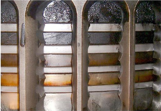
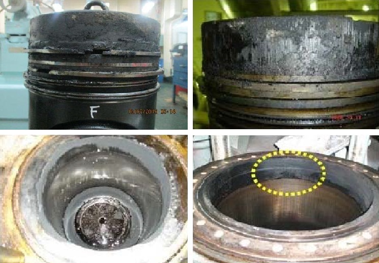
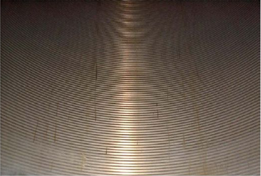 1. BEST CONDITION: Machining mark remains completely.
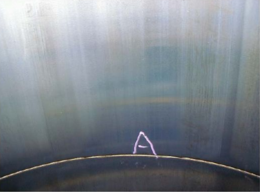 2.ORDINARY CONDITION: Machining mark has been disappeared/ Liner surface smooth & well lubricated.
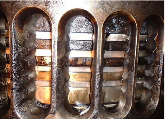
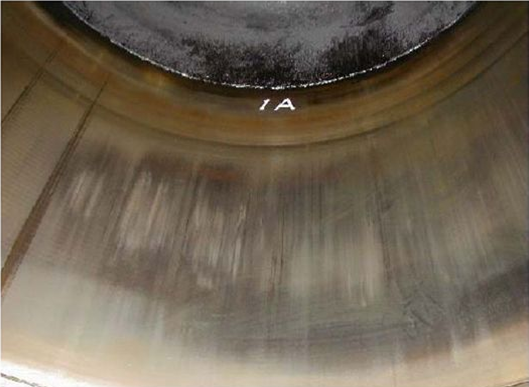 3. BAD CONDITIION: Dark patches on liner/ Scoring marks visible/ Liner surface dry.
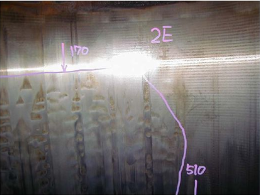 4. SULPHURIC ACID CORROSION: Low temperature corrosion.
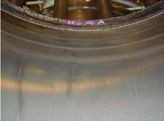 5. STEP WEAR & CRACK: There is step wears at position of TDC, also vertical crack can be seen.
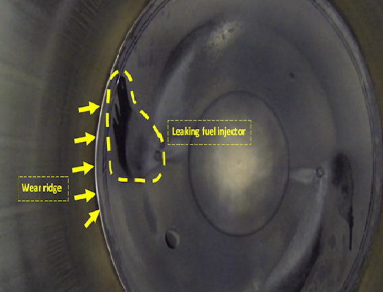 6. Fuel injector leaking/faulty
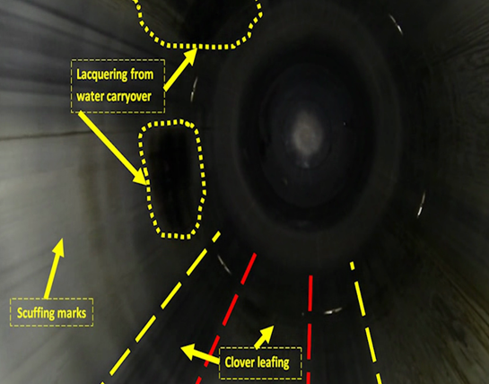 7. Clover leafing of cylinder liner
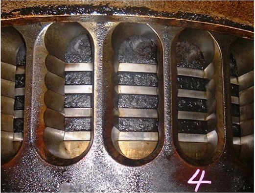 4. WORSE CONDITION: Exhaust gas is sealed at # 4 ring.
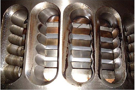
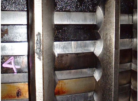 5. PISTON RING SCUFFING: Scuffing can be seen at all piston rings/ Micro seizures can be seen on ring surface/ Edges of rings are shart due to wear.
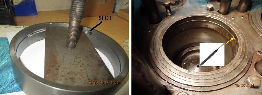
 The Main Configuration With The Double S-lock And Gas Relief Grooves Remains Unchanged. The CL Grooves On The Runing Side Have Been Omitted And Replaced With A Number Of Ports Milled Into The Lower Side Of The Piston Ring These Passages Have Been Configured With A 90 Degree Narrowing, Causing The Ring To Increase The Bypass Area As The Ring Wears, Instead Of Reducing It When The Minimum Depth Is Reached, As Is The Case With The CL Grooves.


 Power Piston