Maintenance and Training of LSA and FFA on Ship

Poor Maintenance Of Life Saving Appliances (LSA) A

Poor Maintenance Of Life Saving Appliances (LSA) And Fire Fighting Appliances (FFA) On Board The Vessel And Improper Training Of Crew May Cause PSC Deficiency, Which May Led To Fine Or Unnecessary Delay In Ship’s Operation. Care Must Be Taken While Doing Maintenance Of LSA And FFA To Avoid Above Situations. Also Training Of Ship’s Personal Should Be Done According To The Company’s Procedures.   

Maintenance Of LSA And FFA
All LSA And FFA Equipments Must Be Kept In Good And Apparent Condition.
LSA And FFA Equipment Must Be Available At All The Times For Immediate Use.
Manufacturer’s Instruction And Guidelines Must Be Followed Strictly To Check Time To Time In Order To Keep It In Good Condition.
Responsible Officer Must Supervise And Report To Master, If Any Defect Noticed. However, Safety Is Responsibility Of All Personals On Board  in This Regard  and Crew Must Be Alert All Times And Report Any Defect/deficiency Noted On LSA And FFA To Chief Officer Who In Turn Will Advise Master Or Chief Engineer So As To Rectify The Same.

Training Of Crew
Training Of Crew Is Must To Ensure That All The Crew Members Are Familiar With Use And Operation Of LSA And FFA. The Master Has The Responsibility To Ensure That The Company’s On Board Training Programme Is Implemented Properly.
This Training Shall Be Implemented Through:
Safety And Pollution Prevention Drills .
Security Drills, Safety And Security Meetings.
On Board Training Presentation By Audio-visual DVDs.

All The Crew Member Individually Must Be Able To Demonstrate Lowering Of Life Boat/rescue  boat, Fully Operate All Fire Fighting Equipments, Don Immersion Suits And Fire Man’s Outfits With SCBA Etc. Apart From The Importance Of Seafarer’s Knowledge And Training Significant Role For Promotion Of Safety On Board The Ship Has To Be The Safety Culture Of The Seafarer.

SOLAS Requirements for Lifeboat launching

Launching, Retrieving, Maintaining Of Lifeboats Is

Launching, Retrieving, Maintaining Of Lifeboats Is A High-risk Activity Particularly Whilst At Sea, And As Such As It Should Be Approached In Way That All Hazards Are Identified And Mitigated. Seafarers Must Know The Solas Requirements And IMO Guidelines For Life Boat Launching Procedures.

What Are The SOLAS Amendments For Life Boat Launching And When Did They Come Into Practice?
Amendments To The International Convention For The Safety Of Life At Sea (SOLAS) Aimed At Preventing Accides During Lifeboat Launching Entered Into Force On 1 January 2013.
According To The Amendments Adopted In May 2011 And The New Paragraph 5 To SOLAS Regulation III/1, Lifeboat On-load Release Mechanisms Not Complying With The New International Life-Saving Appliances (LSA) Code Requirements, Have To Be Replaced, No Later Than The First Scheduled Dry-docking Of The Ship After 1st July 2014 But, In Any Case, Not Later Than 1st July 2019.
The SOLAS Amendment Is Intended To Establish New, Stricter, Safety Standards For Lifeboat Release And Retrieval Systems And Requires The Assessment And Possible Replacement Of A Large Number Of Lifeboat Release Hooks.

Why Do Majority Of Lifeboat Accidents Take Place And What Are The Measures Take To Overcome Them?
The Majority Of Accidents Related To Lifeboats Generally Result From Lack Of Familiarity With Equipment, Inadequate Maintenance, Unsafe Practice During Lifeboat Drills And Inspections/test, Failure Of Communications, And Failure Of Involved Personnel To Assess The Relevant Risks And Take The Required Measures. These Factors Have Been Exacerbated In Many Cases By The Design And Instructions Provided By The Manufacturers.
          The Design Of Some Equipment And Manufacturers’ Instructions With Regards To Repair And Maintenance, May Require Special Attention And Training Of Ship’s Personnel In Order To Attain The Required Level Of Familiarity To Overcome Risks. Also Particular Attention Must Be Paid To The Authorized By Manufacturers Service Engineers When They Attend The Maintenance Or Inspect The Various Critical Parts Of The Lifeboats (winches, Release Mechanism), Bearing In Mind That Human Errors Apply Also To Them.

What Is The IMO Guidelines For Correct Launching Procedure For Conventional Lifeboat?
CONVENTIONAL LIFEBOATS
During Abandon Ship Drills, When Lowering And Manoeuvring Is In Process, The Life Boats Should Never Be Lowered Simultaneously. When The First Life Boat Has Been Safely Recovered And Secured On Board, Only Then The Crew May Proceed With The Lowering Of The Second Life Boat.
Ship’s Staff Should Always Remember That The Setting And Maintenance Of The Release Gear And The Lifeboats Winch Are Critical To The Safe Operation Of Lifeboats And The Safety Of Personnel In The Lifeboat. All Inspections, Maintenance, Operations And Tests Of This Equipment Should Therefore Be Carried Out With Utmost Care And After Having Conducted Risk Assessment. Moreover, Evidence (photos) Of Testing Of The Release Gear Should Be Sent To The Office, Via Crew Mail, On A Monthly Basis.
          Procedures For Each Type And Maker Of Lifeboat Should Be Regularly Reviewed To Ensure They Contain Correct Actions And Precautions, Which Must Be Carefully Followed As Laid Out.
It Is Imperative That The Crew Fully Understand The Operation Of All Equipment, Especially Of Winches, Davits And Release Gear, In Order To Ensure That Mechanisms Are In Good Order And All Safety Interlocks Have Been Checked And Confirmed In Place.
          Review And Understand The Lifeboat Manufacturers’ Specifications And recommendations For Operations And Maintenance.
– No Person Must Enter The Lifeboat After Its Fist Lashing Has Been Removed.
– Before Placing Persons Onboard A Lifeboat, Same Must First Be Lowered One (1) Meter Above The Water And Recovered Without Persons On Board To Ascertain That The Arrangement Functions Correctly. Upon Recovery, Ch. Enginer Shall Check And Inspect Indicators And Associated Equipment.
– The Lifeboat Should Be Lowered Into The Water With Only The Number Of Persons On Board Necessary To Operate The Boat. One Experienced Deck Officer And One Engineer Officer Must Be Among Them.
– No Modification (drilling For Locking Pin Insertion Point ) To On Load Release Hooks Shall Take Place And Existing Locking Pins Must Have Clear Instructions Nearby, For Easy And Fast Guidance And Be Coloured On The Insertion Point, As Addressed In MSC.1/Circ.1205. In Addition, A Warning Notice For The Handle Of The Locking Pin, That It Must Be Removed Before Activating The Release Mechanism, Should Be Placed- The Lifeboat Should Be Lowered Into The Water Only If Suitable And Certified Fall Preventive Device Is Fitted At Both Lifeboat Hooks.
– The Responsible Officer Must Ensure That Lifeboat FPDs Are Properly In Place Before Commencing Any Drill. Please See Photos Below For Your Further Guidance.
The FPDs Should Be Used Only For Drill Purposes, Or In The Event Of Launching And Recovery Of The Life Boat In Water For Non-emergency Purposes (i.e Inspection), And Should Be Safely Stored Inside The Lifeboat, After Completion Of Same. The Reason For Use Of The FPD Is Because It Protects The Crew In Case The Boat Is Unintentionally Disconnected From The Falls. For This Reason, The Use Of FPD Should Be Part Of The Training Onboard And Crew Should Be As Familiar With Them As With Other Parts Of The Operational Equipment Of The Boat. Training Of The Crew Must Contain The Operations That Have To Be Carried Out At The Bow And Stern Hooks For Using The FPD- On Completion Of Operation Personnel Must Leave The Boat When It Reaches The embarkation Deck, And Before The Boat Is Secured.
– The Whole Operation Must Be Carried Out Under The Supervision Of Master And Chief Engineer.
In This Respect, Organizations And Reputable Third Parties Have Taken Actions To Minimize Accidents.

What Guidines Are To Be Followed For Launching Free Fall Life Boat According To IMO?
In Line With SOLAS Chapter III Regulation 19 Para 3.3.4, “free Fall Life Boats Must Be Lowered In The Water At Least Once Every Three Months During An Abandon Ship Drill The Crew Shall Board The Lifeboat, Properly Secure Themselves In Their Seats And Commence The Launch Procedure Up To But Not Including The Actual Release Of The Lifeboat (i.e., The Release Hook Shall Not Be Released).
The Lifeboat Shall Then Either Be Free-fall Launched With Only The Required Operating Crew On Board, Or Lowered Into The Water By Secondary Means Of Launching Without The Operating Crew On Board, And Then Manoeuvred In The Water By The Operating Crew. At Intervals Of Not More Than Six Months, The Lifeboat Shall Either Be Launched By Free-fall With Only The Operating Crew On Board, Or Simulated Launching Shall Be Carried Out In Accordance With The Guidelines Developed By The Organization”.

To Sum Up, Technically, As Per Above SOLAS Regulation The FFLB Must Be:
A. Lowered And Manoeuvred In The Water At Intervals Not Exceeding The Three (3) Months Using Life Boat Davit (secondary Mean).
1. The Entire Crew Will Enter The Life Boat And Take Their Respective Position.
2. The Crew Will Start And Test Life Boat Engine Ahead And Astern As Well As Boat’s Steering Port And Starboard.
3. The Crew Will Exit From The Life Boat.
4. The Boat Shall Then Be Launched In The Water By Secondary Means (davit) With NO Crew Inside. Make Sure That The Life Boat Will Remain Properly Moored Next To Vessel.
5. Operating Crew Shall Proceed To The Life Boat Using The Rescue Boat.
6. Once The Operating Crew Reach The Life Boat, The Life Boat Shall Then Be Manoeuvred In The Water By The OPERATING Crew Only.
7. After Completion Of Manoeuvring, Operating Crew Will Exit From The Life Boat After Having Prepared The Boat For Recovery.
8. Operating Crew Return To The Vessel.
9. Life Boat Recovered Using The Davit.

B. Lowered And Manoeuvred In The Water By Free Fall Launching Every Six Months. However, There Is NO Need To Free Fall Launch The Life Boat, Provided That SIMULATED LAUNCHING Has Been Conducted At Interval Not Exceeding The Six months, As Is Mentioned Above.

GUIDELINES FOR THE SIMULATED LAUNCHING OF FREEFALL LIFE BOATS
The Purpose Of These Guidelines Is To Provide A Basic Outline Of Essential Steps To Safely Carry Out Simulated Launching. These Guidelines Are General; The Lifeboat Manufacturer’s Instruction Manual Should Always Be Consulted Before Conducting Simulated Launching. Simulated Launching Should Only Be Carried Out With Lifeboats And Launching Appliances Designed To Accommodate It, And For Which The Manufacturer Has Provided Instructions. Simulated Launching Should Be Carried Out Under The Supervision Of A Responsible Person Who Should Be An Officer Experienced In Such Procedures.
Typical Simulated Launching Sequence
1. Check Equipment And Documentation To Ensure That All Components Of The Lifeboat
And Launching Appliances Are In Good Operational Condition.
2. Ensure That The Restraining Device(s) Provided By The Manufacturer For Simulated Launching Are Installed And Ensure And That The Free-fall Release Mechanism Is Fully And Correctly Engaged.
3. Establish And Maintain Good Communication Between The Assigned Operating Crew And The Responsible Person.
4. Disengage Lashings, Grips, Etc., Installed To Secure The Lifeboat For Sea Or For
Maintenance, Except Those Required For Simulated Free-fall.
5. Participating Crew Board The Lifeboat And Fasten Their Seatbelts Under The Supervision Of The Responsible Person.
6. All Crew, Except For The Assigned Operating Crew, Disembark The Lifeboat. The Assigned Operating Crew Fully Prepares The Lifeboat For Free-fall Launch And Secures Themselves In Their Seats For The Release Operation.
7. The Assigned Operating Crew Activates The Release Mechanism When Instructed By The Responsible Person. Ensure That The Release Mechanism Operates Satisfactorily And, If Applicable, The Lifeboat Travels Down The Ramp To The Distance Specified In The Manufacturer’s Instructions.
8. Re-secure The Lifeboat To Its Stowed Position, Using The Means Provided By The Manufacturer And Ensure That The Free-fall Release Mechanism Is Fully And Correctly Engaged.
9. Repeat Steps 3-7 Above, Using The Back-up Release Mechanism When Applicable.
10. The Assigned Operating Crew Disembarks The Lifeboat.
11. Ensure That The Lifeboat Is Returned To Its Normal Stowed Condition. Remove Any Restraining And/or Recovery Devices Used Only For The Simulated Launching Procedure

Safety System for Switch Board and Generators

Apart From Direct Temperature Measurement Of The S

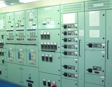
Apart From Direct Temperature Measurement Of The Stator Windings And The Internal Air, The Protection Of A Generator Is Largely Based On The Sensing Of Current And Voltage From Current Transformers (CT) And Voltage Transformers (VT). The Number And Type Of Protective Relay Functions Increase With The Generator KVA Rating And Voltage Level. Protective Relays Are Electromagnetic (traditional) Or Electronic (increasingly More Common) Which Are Mounted On The Generator Front Panel Of The Main Switchboard. Some Protective Functions May Be Grouped Together Within A Single Relay Case. Settings For Level And Time-delay Must Be Periodically Checked By Injecting Currents And/or Voltages Directly Into The Relay (usually Via A Special Multi-pole Socket Adjacent To The Relay And Internally Wired To It). 

Some Typical Relay Types Employed For Generator Protection Are Outlined In The Figure On The Left.
i) OCIT (Over Current Inverse Time Relay)
The Over Current Inverse Time Relay Monitors General Balanced Overloading And Has Current/time Setting Determined By The Overall Protective Discrimination Scheme.

ii) OC (INST) (instantaneous Trip)
Instantaneous Trip To Protect Against Extremely High Overcurrent Caused By A Short-circuit Fault.

iii) NPS (Negative Phase Sequence)
A Negative Phase Sequence Relay Determines The Amount Of Unbalance In The Stator Currents That Is An Indirect Measure Of The Generator Stator And Rotor Temperature. A Relatively Small Degree Of Unbalance Causes A Significant Temperature Rise So The NPS Current Setting Is Low At Around 0.2.ln.

iv) DIFF (Differential Current)
This Is A Differential Measurement Of Current At Each End Of A Stator Phase Winding. This Comparison Of Current Is To Detect An Internal Fault In The Stator Windings That May Be Caused By Partially Short-circuited Coil Turns And/or Earth Faults.
Current Settings For This Very Serious Fault Are Very Low E.g. About 0.1.In. 

v) DEL (Earth Leakage)
An Earth Leakage Relay (sometimes Called Zero Phase Sequence) Detects An Earth Fault Current Returning Back Through The Earthed Neutral Connection. In A Ship's HV Generator System The Earth Fault Current Is Limited By A High Impedance NER (neutral Earthing Resistor) Or Earthing Transformer So The Pick-up Current Setting Is Very Low, E.g. 1-5A With A Time Delay Of 0.1- 0.5 S.

vi) UV /OV (Under Voltage And Over Voltage)
Under Voltage And Over Voltage Functions Are Monitored By These Relays With Settings Of Around 0.8. Un And 1.2. Un Respectively (Un = Rated Voltage) With Time Delays Of About 2s. An Overvoltage Function May Not Be Required In Many Protection Schemes.

vii) UP/OF (Under & Over Frequency)
Under And Over Frequency Settings Are Typically 58 Hz And 62 Hz For A 60 Hz System.

viii) LO (Lock Out Or Trip)
This Is The Master Lock Out Or Trip/hand-reset Relay Responsible For Tripping The Generator Circuit Breaker. Its Action Is Instantaneous When Triggered By A Protective Relay. It Can Also Be Used To Trip The Generator Prime-mover And Initiate Generator Field Suppression Together With The Signalling Of An Alarm.

ix)    RP (Reverse Power)
Generators Intended To Operate In Parallel Must Have Reverse Power Protection (RP).
A Reverse Power Relay Monitors The Direction Of Power Flowing Between The Generator And The Load. If A Prime-mover Failure Occurred The Generator Would Act As A Motor. The Reverse Power Relay Detects This Fault And Acts To Trip The Generator Circuit Breaker.
          The Pick-up Power Level Setting And Time-delay Setting Are Adjustable And Are Pre-set To Suit The Prime Mover. If The Prime Mover Is A Turbine, Very Little Power Is Absorbed When Motoring And A Reverse-power Pick-up Setting Of 2-3% Is Usual. If The Prime Mover Is A Diesel Then A Setting Range Of 5-15% Is Usually Adopted. A Time Delay Range Of About 0.5-3 S Is Usual.
          The RP Relay Operation Is Easily Checked During A Generator Changeover. The Outgoing Generator Is Gradually Throttled Down So That It Motors Causing The Reverse Power Relay To Trip Its Generator Circuit Breaker.

x)Preferential Trip
To Maintain Generator Operation During An Overload, A Preferential Load Shedding Arrangement Is Employed. This Is Achieved By A Special Overload Relay, Called A 'preference Trip Relay'.
         If A Generator Overload Develops, The Preference Trip Sets An Alarm And Acts To Trip Selected Non-essential Loads. This Reduces The Generator Load So That It May Continue To Supply Essential Circuits.
          Each Generator Will Have Its Own Circuit Breaker That Is Typically High Set At 150% With A 20 Seconds Delay.
In Addition, Each Generator Has Its Own Preference Overload Trip, This Being Low Set Generally At 110% Current, Instantaneous Operation. 

If A Generator Overload Condition Develops, Its Preference Overload Trip Will Operate To Energise The Timing Relay. The Timing Relay Then Operates To Disconnect Non-essential Services In A Definite Order At Set Time Intervals, E.g.
1st Trip air Conditioning And Ventilation – 5 Seconds
2nd Trip – refrigerated Cargo Plant – 10 Seconds
3rd Trip – Deck Equipment – 15 Seconds

This Order Of Tripping Obviously Varies With The Ship Type. When Sufficient Non-essential Load Has Been Disconnected, The Preference Overload Trip Resets And No Further Load Is Disconnected. 
          Once A Machinery Has Tripped, Its Switch Will Have To Be Reset.The Generator Preference Trip System Can Also Be Initiated By Low Generator Frequency Or By Low Speed At The Generator Prime Mover. 

In Many Cases The Preference Trip Protection Is Incorporated In A Combined Electronic Relay That Also Monitors Generator Overcurrent And Reverse Power. 

To Maintain The Preference Relay Trip Settings As Originally Specified They Must Be Periodically Tested By Calibrated Current Injection. Preferential Load Shedding, Generator Scheduling And Load Sharing Is Usually Part Of An Overall Power Management System (PMS) Under Computer Control.

Class of Fire and type of Extinguishers used

Fire On Board Is A Very Critical Situation. Correc

Fire On Board Is A Very Critical Situation. Correct Knowledge About The Class Of Fire And What Type Of Extinguishers To Be Used Can Help People On Board  to Fight Fire And Prevent Its Spread.

Q1.  What Is A Fire & How It Occurs?
Fire Is A Chemical Reaction, Giving Off Heat And Light.  
For Fire To Occur Three Elements Are Required :
I) Oxygen
Ii) Fuel 
Iii)Heat
 
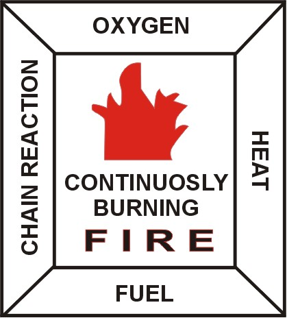
The Above 3 Elements Form The Fire Triangle.  If Any One Of The Three Sides Of The Triangle Is Removed, The Triangle Will Collapse And Hence There Will Not Be Any Combustion.  The Principle Of Fighting Fire Is To Remove One Side Of The Fire Triangle.

Q2. What Do You  mean By Fire Tetrahedron?
"Chain Reaction" Is The Fourth Element Added To The Triangle To Define A Continuously Burning Fire, Which Is Known As The Fire Square Or A Tetrahedron.  

 Q3. What Are The Basic Ways To Fight Fire ?
1. Starving :  By Which The Fire Triangle Is Starved Of The Fuel Or Inflammable Material.  Remove The Inflammable Material And The Fire Will Burn Itself Out.
2. Smothering :  Is Like Asphyxiation – Take The Breath Out.  If There Is No Oxygen In The Air We Will Not Be Able To Live.  Likewise For Fire Oxygen Is Very Important And If That Element Is Removed Or Reduced To Below 15% Then The Fire Will Be Put Off.  Examples Of Smothering Agents Are CO2, Inert Gas, Foam.
3. Cooling :  If The Substance Is Cooled Until It Does Not Give Off Sufficient Vapours To Support Combustion, Then The Fire Will Be Extinguished.  Water Is A Good Example Of A Cooling Agent.
4. Inhibition :  Is The Process Of Interfering With And Stopping The Chemical Reaction In The Fire.

We Have Seen The Four Basic Ways Of Fighting Fire. The Method Of Extinguishing A Fire Depends On The Class Of Fire.  For Example, In Case Of An Oil Fire, Water Will Not Be Useful Though It Is The Best Cooling Agent. We Must Understand The Types Of Fire And The Method By Which To Extinguish.  

Q4. Describe The Classification Of Fire & Extinguishing Medium Used 
Class A Type Fire Involvs Wood, Paper,textiles, Fabrics, Plastics Etc. Water, CO2 And Foam Is  recommended To Be Used In Special Circumstances
Class B Type Fire Involving Combustible Liquid Or Liquefiable Solids. Water Spray, Foam, Dry Chemical Powder (DCP),etc Recommended To Be Used In These Circumstances.
Class C Type Fires Involving Gases Or Liquefied Gases. Shut Off The Supply Use Chemical Dry Powder To Extinguish These Type Of Fires.
Class D Type Fires Involving Metals. Special Dry Extinguishing Medium To Be Medium Used.

Some Sources Regard Electrical Fires As A Different Class Of Fire And In Such A Case Only Dry Powder Extinguisher Or CO2 Extinguisher Should Be Used.

Q5. What Type Of Extinguisher Found On Board Vessels ?
Normally Four Types Of Portable Extinguishers Are Found On Board For Extinguishing A Fire :
1. Foam Extinguishers
2. CO2 Extinguishers
3. Dry Chemical Powder (DCP) Extinguishers 
4. Water Extinguishers

Immersion suit testing and maintenance as per Solas

An Immersion Suit Is A Life Saving Appliance Carri

An Immersion Suit Is A Life Saving Appliance Carried Onboard. It Is A Dry, Waterproof Suit That Protects The Wearer From Hypothermia From Immersion From Cold Water, After Abandoning A Sinking Or Capsized Vessel.

What Is The Solas Regulation For The Testing Of Immersion Suit?
To Ensure The Maintenance Of Adequate Strength And Watertightness Of Seems And Closures Of Immersion Suits And Anti-exposure Suits With Age, It Is Recommended That Each Suit Be Subjected To An Air Pressure Test As The Following, At Intervals Not Exceeding Three Years, Or More Frequently For Suits Over Ten Years Of Age.
A Suitable Head Piece, Fitted With A Means To Inject Air Into The Suit, Should Be Inserted Into The Face Orifice Of The Suit And Secured So As To Minimize Leakage Around The Face Seal.a Low-pressure Monitoring Device, Either Integral To The Fitting For Air Injection Or As A Separate Device, Should Also Be Inserted.
If The Suit Is Fitted With Detachable Gloves And/or Boots, The Wrists And/or Cuffs Should Be Sealed By Inserting A Short Lenght Of Suitable Diameter Plastic Pipe And Securing The Gloves And/or Boots With Suitable Wire Ties Or Hose Clamps.the Zipper Should Be Fully Zipped, And Any Face Flap Closed.
The Suit Should Then Be Inflated To A Pressure Fo 0.7 To 1.4 Kpa (0.1 To 0.2 Psi) If An Auxiliary Inflatable Means Of Buoyancy Is Provided, It Should Be Inflated Through The Oral Valve To A Pressure Of 0.7 Kpa (0.1 Psi) Or Until Firm To The Touch.
Each Seam And Closure Of The Suit-and Each Seam, Oral Tube And Attachment Points And Joint Or Valve Of Any Auxiliary Inflatable Means Of Buoyancy Should Then Be Covered With A Soapy Water Solution Containing Enough Soap To Produce Bubbles (if Leakage Is Noted At A Foot Valve To The Extent That Air Pressure Cannot Be Maintained, The Valves Should Be Sealed For The Test).
If Leaks Are Revealed By The Propagation Of Bubbles At Seams Or Closures, The Leaking Areas Should Be Marked And, After Cleaning The Suit Thoroughly With Fresh Water And Drying It, Repaired In Accordance With The Suit Manufacturer’s Recommendations. The Air Pressure Test May Be Carried Out On Board Ship If Suitable Equipment Is Available. This Test Do Not Adequately Address Deterioration Of Seems And Closures (zippers, Etc.) Which May Not Be Readily Apparent By Visual Inspection. Such Deterioration Can Be Detected By Pressurization Of The Suit With Air, And Testing Of The Seams And Closures For Leaks With A Soapy Water Solution.

– All Cargo Vessels Should Now Carry One  immersion Suit For Every Person Onboard (as Indicated In The Record E Of The Cargo Ship Safety Equipment Certificate)
– Additional Immersion Suits May Be Required At Remotely Located Watch Or Work Stations, Depending On The Design Of The Vessel And Flag State.
– Vessels Trading Solely In Tropical Waters May Be Exempted By Flag State. No Exemption Is Granted To The Bulk Carriers.

What Are The Maintenance To Be Carried Out For Immersion Suit?
When Carrying Out The Inspection Of Immersion Suits And Anti-exposure Suits Required By Solas Regulation Iii/20.7,the Following Procedure Is Recommended:
1. Check Closures On Storage Bag As Well As General Condition Of Bag For Ease Of Removal Of Suit. Ensure Donning Instructions Are Legible. Confirm That Suit Is The Type And Size Identified On The Bag.
2. Lay The Suit On A Clean, Flat Surface. Make Sure The Suit Is Dry Inside And Out. Visually Check For Damage. Rips, Tears Or Punctures Should Be Repaired In Accordance With Manufacturer’s Instructions By A Suitable Repair Station (one Authorized By The Manufacturer And/or Acceptable To The Administration).
3. Check The Zipper By Sliding It Up And Down To Check For Ease Of Operation, Using Lubricant Recommended By The Manufacturer, Lubricate The Front And Back Of The Zipper And The Slide Fastener.if The Zipper Is Not Functional,the Suit Should Be Removed From Service And Discarded Or Returned To The Manufacturer Or A Suitable Repair Station.
4. If Fitted, Check Inflatable Head Support And/or Buoyancy Ring For Damage And Ensure That It Is Properly Attached.check Inflation Hose(s) For Deterioration.at Least Quarterly, The Head Support/buoyancy Ring Should Be Inflated And Tested For Leaks (this Test Does Not Apply To Integral Inflatable Lifejackets) Leaks Should Be Repaired In Accordance With Manufacturers’ Instructions By A Suitable Repair Station
5. Check Retro Reflective Tape For Condition And Adhesion. Replace If Necessary.
6. If Fitted, Check Whistle And Expiration Date Of Light And Battery.
7. Replace Suits In The Bag With Zippers Fully Opened
8. The Opportunity Should Be Taken At Such Monthly Inspections For The Crew To Practise Donning The Immersion Suits Or Anti-exposure Suits.
 

FAQ Orals MEP (Scavenging & Scavenge Fire)

Question Answer On The Topic Scavenging And Scaven

Question Answer On The Topic Scavenging And Scavenge Fire

What Is Scavenging?
The Process Of Exchanging Gases Present In The Combustion Spaces After Combustion With The Charged Fresh Air Is Called Scavenging.
 
What Is Uniflow Scavenging?
With Uniflow Scavenging, The Incoming Air Enters At The Lower End Of The Cylinder And Leaves At The Top. The Advantage Of Uniflow Is The Simple Design Of The Liner, Plus It Is The Most Efficient.

What Is Cross Flow Scavenging?
In Cross Flow Scavenging, The Incoming Air Is Directed Upwards, Pushing The Exhaust Gases Before It.  The Exhaust Gases Then Travel Down And Out Of The Exhaust Port.  Advantage Is No Exhaust Valve.
 
What Is Loop Scavenging In A 2-Stroke Engine?
Loop Scavenging Is Where The Incoming Air Passes Over The Piston Crown, Then Rises Towards The Cylinder Head Forcing Exhaust Gases Down And Out The Exhaust Ports, Just Above The Inlet Port.  The Advantage Of Loop Is That No Exhaust Valve Is Required.
 
What Is Compression And Explain Why Compression Is Required?
Compression Is Where The Air That Is Drawn Into The Cylinder Is Compressed On The Upward Stroke Of The Piston, Both Inlet And Exhaust Valves Being Closed On This Stroke.  As The Air Is Compressed By The Rise Of The Piston, The Air Temperature Is Consequently Raised.  As The Piston Reaches The TDC, Fuel Is Injected, Causing Ignition And Very Rapid Rise In Pressure Of The Gases Forcing The Piston Down.
 
 
What Could Start A Scavenge Fire?
The Main Cause Of A Scavenge Fire Is The Fouling Of Scavenge Spaces By The Blow By Of Products Of Incomplete Combustion Caused By Incorrect Cylinder Lubrication, Faulty Fuel Injection Equipments, Accumulation Of Such Mixtures In The Scavenge Space Can Be Set Alight By Sparks Or Flame Blow By.
 
What You Can Do To Prevent Scavenge Fires?
Conscientious Maintenance Of The Engine And Regular Inspection And Cleaning Of Scavenge Air Spaces Will Help Prevent Scavenge Fires.
 
What Are The Symptoms Of A Scavenge Fire?
When A Scavenge Fire Has Broken Out, The Scavenge Air Temperature And The Exhaust Temperature Of The Unit In Question Will Increase Considerably And In Some Cases The Turbocharger May Start Surging.  Even Hot Spots On The Scavenge Trunking Can Be Found.
 
What Would You Do In The Event Of A Scavenge Fire?
If A Scavenge Fire Were To Start, The Two Main Objectives Are To Confine The Scavenge Fire To The Scavenge Space And To Minimise Damage To The Engine.
In The Event Of The Fire Breaking Out, Inform Bridge That The Engine Is To Be Brought To Dead Slow Ahead And Also Inform The Chief Engineer.
The Fuel Should Be Cut Off To That Particular Cylinder.  The Cylinder Lub Oil Should Be Increased To Prevent Seizure And Wear.
If Fixed Fire Fighting Equipment Is Attached To The Scavenge Trunking, This Can Be Brought Into Operation, Depending On Severity Of Situation.  But In Most Cases The Fire Will Generally Subside Within 5-15 Minutes.
Once The Fire Is Out And Navigational Circumstances Allow It, The Engine Must Be Stopped.
Do Not Open Scavenge Space Doors Or Crankcase Doors Before Site Of Fire Has Cooled Down.  When Opening Up, Care Must Be Taken To Keep Clear Of Any Flame.
After Opening Up, All Scavenge Spaces Must Be Thoroughly Cleaned And All Debris Removed.  The Piston Rods And Cylinder Liner Should Be Examined For Surface Blemishes, Straightness, Etc., And The Diaphragm Glands (Stuffing Box) Examined To Ensure That They Are Operational And Not Damaged.
Also Piston Rings Should Be Checked, As Blow By May Have Been The Ignition Source Of The Fire.  If Possible The Piston Head In Question Should Be Renewed At The Earliest Possible Moment And The Damaged Unit Overhauled.
On Engines Fitted With Tie Bolts, It May Be Necessary To Re-tighten The Bolts Adjacent To The Fire.
When Starting The Engine Again, Care Must Be Taken After Switching On The Fuel To The Cylinder In Question, And That Also The Cylinder Lub Oil Quantities Are Reduced To Normal.
What Is Scavenging?
The Process Of Exchanging Gases Present In The Combustion Spaces After Combustion With The Charged Fresh Air Is Called Scavenging.
 
What Is Compression And Explain Why Compression Is Required?
Compression Is Where The Air That Is Drawn Into The Cylinder Is Compressed On The Upward Stroke Of The Piston, Both Inlet And Exhaust Valves Being Closed On This Stroke.  As The Air Is Compressed By The Rise Of The Piston, The Air Temperature Is Consequently Raised.  As The Piston Reaches The TDC, Fuel Is Injected, Causing Ignition And Very Rapid Rise In Pressure Of The Gases Forcing The Piston Down.

5 Point that can help you in getting placements

Points To Be Followed In College To Excel In Place

Points To Be Followed In College To Excel In Placements & Onboard:

Q1. What Should Be Your Focus While You Are In College?
Ans:  Focus On Subjects Like Internal Combustion Engines, Marine Auxiliary, Electrical, Automation, Safety. These Are The Subjects Which Are Important From Ship’s Point Of View For A Marine Engineer.

Q2. What Should I Do If I Face Any Problem In Understanding A Topic?
Ans: Go Online For Your Subject Related Problems. Undergo Research Until You Are Satisfied. You Might Find Most Of The Topics Discussed On Marinelookout. Discussion With Friends Is Very Important, It Enhances Your Understanding Of A Topic, Once Discussed Properly The Topic Becomes Yours.

Q3. Is Only Studying Important?
Ans: Don’t Be A Bookworm, Be Active In College Activities, I Would Suggest Play Some Sports, Because Ship Is Not A Place Where Only Knowledge Matters You Need Be Vigilant, Active And Tough.

Q4. What Are Other Skills Required For Excelling In Placement?
Ans: For Placements, Profile Yourself Such That Soft Skills Like Presenting Yourself In Front Of Interview Panel With Confidence Will Be Very Helpful. You Should Have An Attractive CV And Performance In College Academics Tops The List. If Calibrated, Academics Hold 40% Importance, 20% Co-curricular And 40% Your Answers In Interview. 

Q. 5 What Is The Main Thing An Interviewer Is Looking Out For In You?
Ans: Knowledge Is The Main Criteria For Interview. An Interviewer Takes A Glance Of Your CV And Then Begins With A Set Of Questions, You Might Not Be Able To Answer All Of Them Correctly But What’s Important Is Your Approach Towards The Question, Try Until You Fail, In College You Might Not Know Everything, So Apply Your Logic And Then Answer. Basic Questions On ICE, Auxiliary Machinery And Electrical, You Must Be Able To Answer. You Should Be Courteous And Not Rude, Wishing The Interviewer Is Important. Remember Not To Argue With Him, Even If You Are Sure The Person Is Wrong. Make Sure If There Is Any Dispute, You Can Prove Your Point Either In A Book Or Some Trusted Source.

FAQ Orals MEP (Auxiliary Machinary)

What Is The Primary Function Of The Expansion Valv

What Is The Primary Function Of The Expansion Valve In A Refrigeration System?
The Primary Function Of An Expansion Valve In A Refrigeration System Is To Regulate The Flow Of Refrigerant From The H P Side To The L P Side Of The System.  
The Pressure Drop Causes The Saturation Temperature To Drop, Enabling It To Boil Off At The Low Temperature Of The Evaporator.

What Is The Function Of An Evaporator In A Refrigeration System?
The Function Of The Evaporator Is To Boil Off The Liquid Refrigerant, At The Same Time Cooling The Air.  The Design Of The System And Evaporator Should Be Such That All Liquid Refrigerant Is Boiled Off And The Gas Slightly Superheated Before Returning To The Compressor.

What Is The Function Of The Condenser In A Refrigeration System?
The Function Of A Condenser In A Refrigeration System Is To Condense And Sub Cool The Refrigerant Below Saturation Temperature. 

What Would Cause An Excessive High Pressure In A Refrigeration System?
High Pressure Could Be Caused By Lack Of Cooling Or A Fouled Condenser Or Even Overcharge, But This Is Usually Unlikely.
How Do You Purify HFO?
Heavy Fuel Oil Is Purified Using A Centrifugal Separator, Which Operates By The Principle Of Centrifugal Force Separating Two Liquids, In This Case Fuel Oil And Water By Means Of A Cylindrical Interface Between The Two.  The Positioning Of This Interface Being Very Important For The Correct Operation.

What Is The Difference Between A Clarifier And A Purifier?
A Purifier Removes Water As Where A Clarifier Removes Solid Impurities.
In Some Cases, Both Are Used For Separation Purposes, Firstly The Oil Is Purified, Then Clarified.

What Is The Regulation Regarding Use Of FWG Inshore?
Evaporators Should Not Be Used Within 20 Miles From Shore, Due To Risk Of Pollutants Being Taken Into The Freshwater System.

How Is 15 Ppm Reached In An Oily Water Separator?
15ppm Is Achieved In An Oily Water Separator By Normally Passing Through A Two Stage Separator Where In The First Stage Oil/Water Is Passed Into The Coarse Separating Compartment. Here Some Oil Will Rise To The Top Of The Compartment Due To Its Lower Density, Heating Coils May Aid This.  The Remaining Oil/Water Will Flow Down Into The Fine Separating Compartment And Moves Slowly Between Catch Plates.  More Oil Will Separate Out Onto The Underside Of These Plates And Travel Outwards Until Free To Rise To The Oil Collecting Space.  The Almost Oil Free Water (usually Being At 100ppm At This Stage) Will Then Pass To The Second Stage Of The Separator, Which Is A Filter Unit Comprising Of Two Filter Units.  The First Filter Stage Removes Physical Impurities Present And Promotes Some Fine Separation.  The Second Stage Filter Uses Coalescer Inserts To Achieve The Final De-oiling, Oil/Water Mixture Leaving This Stage At Less Than 15ppm.

What Safety Devices Are Fitted To A Start Air Line? 
Non Return Valve, Flame Traps/Arrestors, Bursting Discs And Safety Valves.

What Fittings Would You Expect To Find On A Start Air Receiver?
Fittings Found On A Receiver Are:  Safety Valve, Fusible Plug, Isolating Valve To Main Air Start System, Filling Valve From Compressor, Drain Valve, Valve To Control Air, Valve To Whistle, Pressure Gauge.

What Are The Safety Devices Fitted To An Air Compressor? 
Low Lub Oil Pressure Shut Down
High Air Temperature Shut Down
1st Stage Relief Valve
2nd Stage Relief Valve
A Fusible Plug Is Fitted After The 2nd Stage Cooler, Set At 120°C
If Water Cooled, A Busting Disc Is Fitted.

What Is The Maximum Compressed Air Temperature That Should Leave An Air Compressor?
93°C

What Is The Purpose Of A Fusible Plug On An Air Receiver And At What Temperature Is It Designed To Melt?
The Purpose Of The Fusible Plug Is To Act As A Safety Feature To Release Compressed Air From The Receiver In The Event Of A Fire In The Vicinity.  The Fusible Plug Is Designed To Melt At 150°C.

Explain How You Would Start An Air Compressor And Stop It (after Overhaul)
Check Oil Level In Crankcase.
Then Ensure All Drains Are Open, I.e. Intercooler Drains And Also Unloaders.
Check Air Intake Filter Is Clean.
Ensure Oil Pressure Gauge Is Open And That Air Pressure Gauges I.e. 1st And 2nd Stage, Are Partially Open To Stop Gauge Fluctuation.
If Water Cooled, Check Valves Are Open And Cooling Is Supplied.  Also Check Header Tank.
Bar Machine Over By Hand To See If It Is Free To Turn.
Start The Machine, Check There Are No Unusual Noises Or Vibrations And Oil Pressure Is Correct.
Then Close Drains And Unloader.
If All Seem Okay, Run For 30 Minutes, After Which, It Can Be Stopped, Covers Removed And Bearings Checked.  If Okay Machine Can Be Started On Automatic And Run.
To Stop The Machine, Always Make Sure The Machine Is Unloaded And Drains Opened Before Stopping, Unless Automatic Drains And Unloaders Are Fitted.

Name The Two Most Common Types Of Coolers Used On Board?
Shell And Plate Type Coolers
Shell Being Where A Tube Stack Is Used And Fitted Into A Shell And Closed At Either End With End Covers.
Plate Type Being Made Up Of A Number Of Pressed Plates Surrounded By Seals And Held Together In A Frame.

How Do You Start Up, And Parallel A Generator?
First Check Engine Oil Levels, Such As Lub Oil Sump, T/C Oil Level, Governor Oil Level, Rocker Arm Bank Oil Level (if Fitted).
Check Jacket Water Header Tank Level
Ensure Indicator Cocks Are Open, Start Lub Oil Priming Pump Then Bar Engine Over (ensure Turning Bar Is Removed).
Kick Engine On Air.  Close Indicator Cocks.
Start The Engine.
Check All Parameters Are Correct:  Lub Oil Pressure/Temperature, Jacket Water Temperature/Pressure, Check Sea Water Cooling Pressure And Rocker Arm Lub Oil Pressure.
Allow Engine To Warm Up And When Satisfied That Everything Is Okay, Engine May Be Paralleled As Follows:
Ensure The Voltage Of The Machine To Be Paralleled Is The Same As The Bus-bar Voltage.  Ensure The Frequencies Of Both Machines Are The Same (the Frequency Of The Incoming Machine Can Be Adjusted Using The Speed Control).
Select The Machine To Be Paralleled On The Synchroscope Selector.
The Synchroscope Should Then Start To Rotate, It Should Be Rotating In A Clockwise Direction Slowly.  If It Is Rotating In An Anti-clockwise Direction, This Means The Speed Of The Incoming Machine Is Too Slow Or If It Is Rotating Fast Clockwise, The Speed Of The Incoming Machine Is Too Fast, This Is Adjusted Using The Speed Control.
When The Needle Of The Synchroscope Is Rotating In The Clockwise Direction Slowly, The Breaker Of The Incoming Machine Should Be Closed.  When The Needle Of The Synchroscope Is At The Five To Twelve Position, This Will Allow The Incoming Machine To Take A Slight Amount Of Load When Coming On The Switchboard And Also Prevent The Machine Tripping On Reverse Power.
The Load Is Then Shared Equally Between Both Machines.

What Is The Purpose Of Rocker Gear On An Engine?
The Purpose Of The Rocker Gear Is To Operate The Inlet And Exhaust Valves On The Cylinder Head.

What Trips Are There On A Generator?
The Trips On A Generator Are:  Lub Oil Low Pressure Shut Down, Jacket Water High Temperature, Overspeed Shut Down.


Baltic Sea Safeties

BALTIC SEA AREA – A MARPOL 73/78 SPECIAL AREA.

​BALTIC SEA AREA – A MARPOL 73/78 SPECIAL AREA.
What Is The Baltic Sea Area Geographically?
The Baltic Sea Area Comprises The Baltic Sea Proper, Plus The Gulf Of Bothnia, The Gulf Of Finland, And The Entrance To The Baltic Sea Bounded By The Parallel Of The Skaw In The Skagerrak At 57 44.43’N. With A Total Area Of About 370,000 Km2, The Baltic Sea Area Is One Of The World’s Largest Brackish Water Basins.

Why Is It Important To Protect The Baltic Area?
The Baltic Sea Area Has Always Been Of Great Importance To The People Living Around It, Providing A Natural Bond As Well As Routes Of Navigation. Fisheries Remain A Valuable Part Of People’s Livelihood And The Baltic Sea Area Is Also A Recreational Resource Of Growing Value.Because Of The Very Specific Hydrographical, Chemical And Physical Conditions Of The Baltic Sea Area, And Its Geological History, It Possesses Quite Unusual Fauna And Flora. Marine And Freshwater Organisms Live Side By Side, And There Is A Number Of Living Relicts. The Exchange Of Water In The Baltic Sea Is Very Slow, And If Harmful Substances Are Introduced They Will Remain There For A Very Long Time.As The Fauna And Flora Of The Baltic Sea Area Are Extremely Sensitive To Changes In Their Environment There Should Be No Discharges Of Harmful Substances, Especially Oil And Noxious Liquid Substances, Into This Vulnerable Sea.

What Are The Conventions In Place To Protect The Baltic Sea?
The Pollution Prevention Regulations To Protect The Marine Environment Of The Baltic Sea Area From Pollution, Every Ship Entering The Area Is Urged To Comply With The Anti-pollution Regulations Of The HELSINKI CONVENTION. This Applies To All Ships, Irrespective Of Whether Or Not They Are Flying The Flag. The Helsinki Convention Growing Awareness That National Measures Alone Are Not Sufficient To Protect This Highly Sensitive Marine Environment Led The Baltic Sea States To Adopt The HELSINKI CONVENTION (Convention On The Protection Of The Marine Environment Of The Baltic Sea Area), Which Was Signed In 1974 And Came Into Force In 1980. The 1974 Convention Was The First International Agreement Worldwide To Take Into Account All Aspects Of Marine Environment Protection.The Convention Aims To Prevent Pollution From Ships (including Dumping), Pollution From Land-based Sources, And Pollution Resulting From The Exploration And Exploitation Of The Seabed And Its Subsoil. The Convention Also Regulates The Co-operation To Respond To Marine Pollution By Oil And Other Harmful Substances. A Revised Convention Was Signed In 1992 In Order To Extend, Strengthen And Modernize The Legal Regime For The Protection Of The Marine Environment Of The Baltic Sea Area.The 1992 HELSINKI CONVENTION Entered Into Force On 17 January 2000.
In Accordance With The International Convention For The Prevention Of Pollution From Ships, 1973, As Modified By The Protocol Of 1978 Relating Thereto (MARPOL 73/78), Under Which The Baltic Sea Area Has Been Designated As A Special Area (regarding Annexes I, Oil, And V, Garbage), Far-reaching Prohibitions And Restrictions On Any Discharge Into The Sea Of Oil Or Oily Mixtures And Garbage Have Been Introduced By The Baltic Sea States.The Discharges Of Noxious Liquid Substances Are Also Strictly Regulated. In Addition, Regulations Concerning The Discharge Of Sewage Into The Sea And The Prohibition Of Incineration Of Shipgenerated Wastes In The Territorial Seas Of The Baltic Sea States Have Been Adopted By The Contracting Parties To The HELSINKI CONVENTION. There Is Also A General Ban On Dumping And Incineration Of Other Wastes, Not Incidental To Or Derived From The Normal Operation Of Ships, In The Entire Baltic Sea Area.
The Discharge Regulations Must Be Strictly Observed Owing To The Vulnerable Marine Environment Of The Baltic Sea Area And In Order To Keep The Shorelines And Beaches Clean.

What Are The Pollution Prevention Meausers For Oil And Cargo Waste Discharges In Place At Baltic Sea?
The Discharge Regulations Are As Follows:
And Refined Products.The Prohibition Applies Not Only To Discharges From The Cargo Tanks Of Oil Tankers But Equally To Discharges From The Machinery Spaces Of Any Ship. Only If The Oil Content In The Effluent Does Not Exceed 15 Parts Per Million Can A Discharge Be Permitted. For Ships Of 400 Gross Tonnage And Above The Oil Filtering Equipment Must Be Provided With Arrangements That Ensure That Any Discharge Of Oil Or Oily Mixtures Is Auto-matically Stopped When The Oil Content In The Effluent Exceeds 15 Parts Per Million. Ships Of Less Than 400 Tons Gross Tonnage, Lfying The Flag Of A Baltic Sea State, Should Comply With Adopted Guidelines Concern-ing Holding Tanks/oily Water Separating Or Filtering Equipment.
Finland Has Prohibited The Use Of Bilge Water Separators In Her Inland Waterways And In The Territorial Waters, Within The Area 4 Nautical Miles From The Nearest Land. Any Discharge Of Oil Or Oily Mixtures Into The Baltic Sea Area Is Prohibited. Oil Means Petroleum In Any Form Includ-ing Crude Oil, Fuel Oil, Sludge, Oil Refusepre-wash Procedure Must Be Applied And Similarly The Residue Must Be Discharged To A Reception Facility Until The Tank Is Empty. There Is A Prohibition On Discharges From Tanks That Have Contained Category X,Y Or Z Substances, Specified By IMO’s Inter-national Bulk Chemical Code, Which Cat-egorizes Noxious Liquid Substances (NLS) Carried In Bulk According To Their Magni-tude Of Harm To The Marine Environment If Discharged, Unless Specific Provisions Of Annex II "Regulations For The Control Of Pollution By Noxious Liquid Substances In Bulk" To MARPOL 73/78 Are Met. Tanks Having Contained Category X Substances Must Be Pre-washed Before A Ship Leaves The Port Of Unloading And The Resultant Tank Washings Must Be Delivered To A Reception Facility.The Concentra-tion Of The Substance In The Effluent To The Facility Must Be At Or Below 0.1% By Weight And The Tank Must Be Fully Emptied.
For High-viscosity Or Solidifying Substances In CategoryY The Specified The Cargo Residues In CategoryY Or Z Must Be Removed To Specified Small Quantities And Any Tank Washings Must Be Discharged To A Reception Facility Of The Port Of Unloading Or Another Port With A Suitable Reception Facility Provided That It Has Been Confirmed That A Reception Facil-ity At That Port Is Available And Is Adequate For Such A Purpose. The Eventual Discharge Of Any Residues Of Substances In Category X,Y Or Z Into The Sea Must Comply With Specific Provisions For Each Substance Category On The Speed Of The Ship, Discharge Below The Waterline, Distance From The Nearest Land And Depth Of Water. The Carriage And Discharge Into The Sea Of Noxious Liquid Substances Which Have Not Been Categorized, Provisionally Assessed Or Evaluated, Or Of Ballast Water, Tank Washings, Or Other Residues Or Mixtures Containing Such Substances Is Prohibited.

What Is The Regulation For Disharge Of Sewage In The Area?
For Ships Engaged In International Voyages In The Baltic Sea Area, Of 400 Gross Ton-nage And Above Or Which Are Certified To Carry More Than 15 Persons Regulations On sewage From Ships Is Prohibited Within 12 Nautical Miles Of The Nearest Land Unless Sewage Has Been Comminuted And Disinfected Using An Approved System And The Distance From The Nearest Land Is Longer Than 3 Nautical Miles. In Any Case, When Discharging From A Sewage Holding Tank, The Discharge Must Be At A Moderate Rate And The Ship Must Be Proceeding En Route At A Minimum Speed Of 4 Knots. Only If A Sewage Treat-ment Plant, Approved According To The Requirements Of IMO, Is Used Onboard, Can The Discharge Take Place At Any Dis-tance From The Nearest Land. surveys And Certification Of Annex IV "Regulations For The Prevention Of Pollu-tion By Sewage From Ships" To MARPOL 73/78 Also Apply.

Explain The Regulations Laid Down For Garbage?
The Discharge Of Garbage In The Baltic Sea Area Is Prohibited. However, Food Wastes May Be Discharged, But In Any Case Not Less Than 12 Nautical Miles From The Nearest Land. Incineration Means The Deliberate Combustion Of Wastes Or Other Matter At Sea For The Purpose Of Their Thermal Destruction, Excluding Activities Incidental To The Normal Operation Of Ships Or Other Man-made Structures.The Baltic Sea Has Been Designated As A SOx Emission Control Area Which Requires That All Ships Navigating In Its Waters Use Fuel Oil With A Sulphur Content Not Exceeding 1.5% M/m Or An Exhaust Gas Cleaning System/any Other Technical Method Reducing The Total Emissions Of Sulphur Oxides From Ships Ensuring The Same Level Of Efficiency.A Bunker Delivery Note Accompanied By A Representative Sample Of The Delivered Fuel Oil Should Be Kept On Board The Ship For Inspection And According To Annex VI "Regulations For Prevention Of Air Pollution From Ships" To MARPOL 73/78. In Accordance With Annex VI Deliberate Emissions Of Ozone-depleting Substances Is Prohibited.
Incineration, Except For The Incineration Of Ship-generated Wastes, Is Prohibited Throughout The Baltic Sea Area. However, The Incineration Of Wastes Deriving From The Normal Operation Of The Ship Is Also Prohibited In The Territorial Seas Of The Baltic Sea States.

How to apply for DCE ?

How To Apply For DCE(Document Of Endorsement) Leve

How To Apply For DCE(Document Of Endorsement) Level 1(Basic)

1. You Need To Have A Valid Seafarer Profile At Dgshipping, Egovernamce Page.
2. You Need To Login Into That Page I.e Esamudra, With Your Indos No. Which Is Your User Id And Your Password.
3. Go To Apply DCE Online Link Which Is Clearly Visible On The Page.
4. When You Enter You Will Find Your Personal Details Already Registered Through Your Profile.
5. You Need To Select Your MMD On Which You Are Going To Apply You Can Apply To Any MMD Of Your Choice.
6. You Will Enter Your Details If You Have COC, Then Your Address Of Residence. Make Sure Its Correct Because If You Select By Post Delivery. DCE Will Be Delivered To This Address.
7. You Will Now Be Able To Generate An Application No. For Your DCE.
8. You Will Have To Pay 3000 INR As Fees.
9. When The Fee Is Paid, Cross Examine Your Application Form.
10. Now Take A Print Out Of That Form.
11.Go To Home Page Now, It Will Have An Icon Named COC  status, Document Upload.
12. When You Enter This Page, You Will Find A Page Where You Will Be Asked To Upload Documents.
13. For A New DCE You Will Have To Upload A Passport Size 3.5cm*3.5 Cm Photograph In .jpg Format.
14. A Scan Copy Of Your Signature Preferably 3.5cm *1.5cm In .jpg Format.
15. A Scan Copy Of Your Documents For Modular Courses Namely Basic Familiarization Course In Oil/Chemical, Advance Fire Fighting & Its Refresher. All These Modular Courses Have To Be Scanned As A Single Document In Pdf Format.
16. A Scan Copy Of The Generated Online Application Form Bearing The Place And Signature Of The Applicant On It.
17. After All The Documents Are Uploaded, Your Status Of Application Will Show Under Process.
18. Generally All The Applications For The Day Are Reviewed In The First Half  i.e. By 12 Noon. 
19. If They Find Any Problem With Documents Or Anything They Will Put A Query Quoting The Problem.
20. If Need Be You Will Have To Re Upload Your Documents.
21. If They Find Everything All Right Your Status Will Be Verified.
22. Within A Week's Time, Your DCE (Document Of Endorsement For Oil And Chemical Tankers) Will Be Delivered To The Given Address.