MEP Oral Question-Answer

What Is The Procedure For Handing Over A Watch?

What Is The Procedure For Handing Over A Watch?
The Engineer Should Not Vacate The Engine Room Until His Relief Arrives.
He Should Acquaint The Relieving Engineer Of Any Abnormal Operating Conditions That Have Occurred During The Watch.
Any Orders From The Bridge, Recorded In The Log Book Should Be Pointed Out.
Instructions From Senior Engineer Should Be Passed On.
Any Repairs Should Be Reported Together With Information On Any Machinery That Has Been Dismantled.
The Presence Of Any Other Members Of Ship's Staff In The Engine Room Should Be Reported.
The Engineer Must Ascertain That His Relief If Fit And Able Before Vacating The Machinery Space.
 
Explain The Bilge System From Bilge Wells To Overboard.
The Bilge Pump (Positive Displacement Pump) Takes Suction From The Bilge Well Via A Strum Box, Then Via A Strainer Before Entering The Pump Where It Is Then Discharged To The Bilge Holding Tank.
From The Bilge Tank The Oily Water Separator Takes Suction, Bilge Water Passes Through The Separator Before Being Discharged Overboard Via 15ppm Monitoring Unit, Which Will Automatically Stop The Oily Water Separator Pump And Give An Alarm If The Oily Water Mixture Exceeds 15ppm.
 
How Is The Signal From The Bridge When The Helm Is Moved Transmitted To The Hydraulic Rams In Steering Flat?
When The Helm On The Bridge Is Moved, Electrical Impulses Are Produced.  These Impulses Are Transmitted Via An Amplifier Or Control Unit To The Steering Flat.  In The Steering Flat, These Impulses Are Relayed To A Servomotor (telemotor) Which Drives An Adjusting Gear And Floating Lever Which Puts The Steering Gear Variable Delivery Pump On Stroke, Thus Creating Hydraulic Pressure In The System Which Moves The Rams, Thus Moving The Tiller And Rudder.
The Pump Is Only Required To Deliver Oil When The Helm Is Moved I.e. Once Rudder Has Matched The Helm Angle, The Control Lever Will Put The Pump Off Stroke.
 
Why Is A Gear Type Pump Used For Pumping Oil, While A Centrifugal Pump Is Used For Pumping Water?
A Gear Pump Is Used For Pumping Oil As It Has A High Suction Lift, Is Self Priming, Able To Produce The Discharge Pressure Required By The System And Can Handle Large Amounts Of Vapour Or Entrained Gases.  It Is Also Able To Pump High Viscous Fluids.
A Centrifugal Pump Is Used For Pumping Water, As It Is Unable To Pump High Viscous Fluids Such As Oil, The Centrifugal Pump Is Not Self-Priming.

What Would Happen To The Amps Of A Centrifugal Pump If It Were Run With The Discharge Valve Shut?
The Amps Would Drop, As There Would Be No Load On The Pump.
 
What Steering Gear Checks Would You Do Before Sailing?
Prior To A Ship's Departure From Any Port, The Steering Gear Should Be Tested To Ensure Satisfactory Operation.  These Tests Should Include:
Operation Of The Main Steering Gear
Operation Of The Auxiliary Steering Gear Or The Use Of The Second Pump Which Acts As The Auxiliary.
Operation Of The Remote Control Systems From The Main Bridge Steering Positions.
Operation Of Steering Gear Using The Emergency Power Supply.
The Rudder Angle Indicator Reading With Respect To The Actual Rudder Angle Should Be Checked.
The Alarms Fitted To The Remote Control System And Steering Gear Power Units Should Be Checked For Correct Operation. 
Steering Gear Header Tank Level Should Be Checked. 
During These Tests, The Rudder Should Be Moved Through Its Full Travel, In Both Port And Starboard And The Various Equipment Items, Linkages, Etc. Visually Inspected For Damage Or Wear.  The Communication System Between Bridge And Steering Gear Compartment Should Also Be Operated.
 
What Are Normal Jacket Water Temperatures And Pressures?
Normal Jacket Water Pressures Are Between 2-3 Bar, Temperatures 80-85°C, Alarm Point At 90°C And Shut Down At 95°C .
What Is The Correct Method Of Starting And Stopping A Centrifugal Pump?
The Correct Way To Start And Stop A Centrifugal Pump Is With The Discharge Valve From The Pump Closed, I.e. Less Load On The Motor When Starting And Stopping.
 
What Would You Do In The Event Of An Oil Spill?
Raise The Alarm, Inform Bridge And Chief Engineer. 
There Should Be A Set Drill For Oil Spills, Which Is Practised Regularly.
If Possible Contain The Spill On Deck And Start Clean Up Procedures Using Appropriate Oil Spill Equipment.
If The Oil Has Spilt Into The Sea:-  If In Port, Port Authorities Should Be Informed.  If At Sea, Coastguard Should Be Informed.
The Time Of Spill Should Be Recorded With The Place Or Position Of Ship At The Time Of Spill Along With Approximate Quantity And Type Of Oil.
Circumstances Of Discharge Or Escape Would Be Logged In Oil Record Book And Engine Room Log Book.
 
Why Are High And Low Suctions Fitted On Fuel Oil Service Tanks?
The High And Low Suctions Are A Safety Feature To Prevent Invertent Shut Down Of Main Engines, Generators And Boilers Due To Water Contamination Of The Fuel.  Normally The Low Suction Is Kept In Use.  If Any Water Should Find Its Way Into The Fuel And Service Tank, It Will Gradually Separate Towards The Tank Bottom.  When It Becomes Apparent Water Is Present By Finding It At The Tank Drains Or By Operation Of The Engine, It Is Possible To Bring The High Suction Into Operation And Avoid Shut Down.
 
Describe The Duties Of A Duty Engineer.
Regularly Check And Record All Pressures And Temperatures In The Engine Room Log.
Pay Attention To Readings For Deviation From Normal, Particular Attention Being Made To Exhaust Gas Temperature, Scavenge Temperatures And Pressures And Turbo Charger Revs.
Adjustments Should Be Made For Sea Water Temperature Changes To Keep Correct Temperatures And Pressures.
Checks Should Be Made On The Pressure Drops Across Fuel And Lubrication Filters To See That They Are Operating Within Required Limits.
Check All Oil Levels In Auxiliary Machinery:  Main Engine Sump Levels, Cylinder Lubricators, Turbo Charges, Governors.
Check Around All Bearings And Crankcase Doors Using Palm Of The Hand To Feel For Any Increase In Temperature.
Ensure That Fuel In The Daily Service Tanks Is At Correct Levels And That It Is Sludged And Drained Of Water.
Depending On Type Of Purifiers Fitted, Sludge And Drain, Check Oil Level, Signs Of Vibration And Clean If Required.
Carry Out All Routine Assignments As Recommended By Engine Builders Or The Company.
At All Times Use Sight, Smell And Hearing, As This Is Often The First Sign Of A Fault Developing In The Engine Room.
Check Bilge Levels, Stern Gland, Air Start Bottles And Maintain Correct Levels And Pressures.
Record And Fuel/Lub Oil Transfers And Any Irregularities In Log.
 
What Are The Uses Of Centrifugal Pumps, Positive Displacement Pumps And Gear Pumps On Board A Ship?
Centrifugal Pumps:  Seawater Cooling Pumps, Jacket Water Cooling Pumps, Boiler Feed Pumps (Multi Stage Pumps)
Positive Displacement Pumps:   Bilge Pumps, Steering Gear Pumps, Cargo Shipping Pumps.
Gear Type Pumps:   Fuel Oil Booster Pumps, Fuel Oil Transfer Pumps, Engine Lub Oil Pumps.
 
Why Are Weighted Cocks Fitted To Sounding Pipes Of Fuel Oil Tanks?
Weighted Cocks Are Fitted To Sounding Pipes Of Fuel Oil Tanks To Prevent Fuel Oil Spills From Overflows.  They Also Prevent Vapours Escaping From Tanks.
 
Describe Different Types Of Cooling Systems I.e. Seawater Cooling System And Central Cooling System.
A Seawater Cooling System Is An Arrangement That Uses Individual Coolers For Lub Oil, Jacket Water And The Piston Cooling System.  Each Cooler Being Circulated By Sea Water.
As Where Some Modern Ships Use A Central Cooling System With Only One Large Sea Water Circulated Cooler.  This Cools A Supply Of Fresh Water, Which Then Circulates To The Other Individual Coolers.  With Less Equipment In Contact With Sea Water, The Corrosion Problems Are Much Reduced In This System.
 
How Many Pumps Are There In The Engine Room That You Can Pump Bilges With?
A Bilge Pump Which Is Normally Positive Displacement.
The Others May Vary From Ship To Ship, But Can Be The Ballast Pump, General Service Pump And Main Sea Water Cooling Pump.  These Pumps Are Only Used For Pumping Bilges In The Event Of An Emergency And Have An Emergency Bilge Suction/Injection Valve Connected To Them.
 
Give Possible Reasons Why The Engine Room Bilge Pump May Not Be Able To Empty Bilges.
The Strum Box From The Bilge May Be Fowled.
Bilge Pump Suction Strainer May Be Blocked.
A Valve May Be Left Open From An Empty Bilge.
There Could Be A Hole In The System On The Suction Side Of The Pump.
Depending On Type Of Bilge Pump, The Pump Suction Or Discharge Valves May Need Overhauling.

Why Would The Bridge Need To Be Informed That The Engine Is About To Be Stopped?
The Bridge Would Need To Be Informed That The Engine Was About To Be Stopped To Ensure It Was Navigationally Safe To Do So, I.e. Not In Busy Shipping Lanes Or Near Land.

Pumps used onboard

What Do You Mean By A Pump?

What Do You Mean By A Pump?
A Pump Is A Device That Transfers Energy To A Fluid Passing Through It. In Practice, Pumps Change Both The Velocity And The Pressure Of The Fluid Passing Through It, The Ratio Of These Energy Changes Depends Upon The Type And The Speed Of The Pump In Use. 

What Are The Main Types Of Pumps?
Main Types Of Pumps
1. Displacement Pumps
2. Kinetic Pumps

What Do You Mean By Displacement Pump? Also Briefly Explain Types Of Displacement Pump.
1. Displacement Pumps
In Displacement Pumps The Volume Of The Pump Chamber Is Alternately Increased To Draw The Liquid In (suction) And Then Decreased To Force The Liquid Out (delivery). This Is Done By A Reciprocating Motion Of A Piston Or Plunger Within A Cylinder, Or By A Rotary Motion Of Specially Designed Vanes, Gears Or Rotors. 
Positive Displacement Are Provided Fitted With Relief Valve Safeguard The System

Types Of Displacement Pump?
i) Reciprocating Pump: A Reciprocating Pump Has 'to And Fro' Motion Provided By A Direct Acting Steam Driven Piston, Or Through Mechanisms That  convent Rotary Motion To Reciprocating Motion (e.g. Cranks, Eccentrics Etc.).Due To Fluctuating Motion Of The Piston, The Delivery And Pressure Is Not Steady. To Improve The Overall Performance, The Pump Is Arranged As Double Acting And Fitted With An Accumulator (air Vessel) On The Discharge Side Of The Pump To Achieve A Near Steady Pressure. 
Reciprocating Type Pumps Are Suitable For Delivering Smaller Quantities Of Liquids At High Pressures. They Are Self-priming And Can Handle High Suction Lifts. However Their Construction Is Complicated And Uneconomical Except For Limited Applications E.g. Bilge Pumps, Stripping Pumps, Etc.

ii) Rotary Pumps
 Rotary Types Of Displacement Pumps Are Commonly Used On Board Ships In Place Of Reciprocating Pumps.
A Rotary Pump Continuously Scoops The Fluid From The Pump Chamber By Means Of Gears Or Screws, Or Vanes Etc. When Rotated, Liquid Gets Trapped In Small Pockets Created By The Moving Element And It Gets Transferred From The Suction Side To The Delivery Side.

Types Of Rotary Pumps

a) A Gear Pump Has Intermeshing Gears Or Lobed Members Enclosed In A Suitably Shaped Housing. The Efficient Of These Pumps Depends Upon The Accuracy With Which The Component Parts Are Machined And Fitted I.e. Working Clearances. Gear Pump Is The Simplest Type Of Positive Delivery Pumps And Most Commonly Used On Board Ship For Handling Small Quantities Of Fluids -usually Oils, E.g. Lubricating Oil Transfer Pumps, Auxiliary Diesel Engine Lubricating Oil Pump, Oil Separator Pumps Etc. Delivery Rate Depends Directly Upon The Speed Of The Pump. 

B) A Lobe-pump Like A Gear Pump And Was The Earlier Type Of Mechanical Pumps Used For Supercharging Of Main Engine. Now You Will Find It Being Used A Sewage Pump.

C) A Vane Type Pump Operation Is Also Based On The Principle Of Increasing The Size Of The Cavity To Form A Vacuum, Allowing The Space To Fill With The Incoming Liquid, And Then Forcing The Fluid Out Of The Pump Under, Pressure By Diminishing The Volume.

        The Sliding Vanes Or Blades Fit Into The Slots In The Rotor. Ahead Of The Slots And In The Direction Of Rotation, Grooves Admit The Liquid Being Pumped By The Vanes, Moving Them Outward With A Force Of 'locking Pressure That Varies Directly With The Pressure That The Pump Is Operating Against. The Grooves Also Serve To Break The Vacuum On The Admission Side. The Operating Cycle And The Action Of Centrifugal Force And Hydraulic Pressure Hold The Vanes In Contact With The Casing. 
       This Type Of Pumps Are Most Suitable For Variable Displacement Requirement E .g. Hydraulic Steering System, Hydraulic Winches Etc. 

iii) Screw Pump: It Is Most Suitable For Viscous Fluids And Is Commonly Used For Medium To Heavy Duty Requirements. (e.g. Main Engine Lubricating Oil Pump, Cargo Pumps, Oil Transfer Pumps Etc.  Screw Pumps Are Broadly Classified By The Number Of Screw Rotors Employed E.g.   

Types Of Screw Pump
a) Single-screw– Rotating Within A Accurately Bored Cylinder -mono-pumps As Commonly Known For Marine Application Has One Power Rotor Within A Semi-flexible Stator, And This Type Can Handle Highly Abrasive Liquids And Can Also Pump Liquids Containing Fairly Large Solid Particles.
b) Two-screw– Either With Intermeshing Contact, Or Separately Driven And Synchronised To Run With Positive Clearance.  
C) Three-screw
-with Three Screw On Parallel Axis. The Central Screw Is Power Driven And Drives Two Outer Idler Screws. The Assembly Of Three Screws Is Usually Supplied In A Single Element.     

What Do You Mean By Kinetic Pumps (Roto-dynamic)?
Centrifugal Pumps Are Most Common Type Of Pumps On Board Ships. Almost All Of The Pumps On Board For Seawater Or Fresh Water Are Of Centrifugal Type. They Come In Various Sizes And Arrangements Of Flow And Stages And Design Of Impellers And Casings.
Flow: Radial, Mixed, Or Axial 
Stage: Single Stage, Multiple Stage
Impellers: Open Or Closed Impellers
Drive: Horizontal Or Vertical Drive.
On Some Ships, Even The Main Engine Lubricating Oil Pump Is Of Vertical Centrifugal Type Located Within The Oil Sump And Driven By Electric Motor Above The Tank Top. These Pumps Are Called Submersed Type Pumps.

Explain Operating Procedures For Displacement Pumps?
Starting:  
Precaution: Never Start A Displacement Pump Without Ensuring That All Valves On The Discharge Line Are Open.  
1. Attempt To Turn The Pump Shaft Manually To Ensure It Is Not Seized.  
2. Ensure That The Cocks To The Pressure Gauges Are In Line For Indicating The Pressure And Not Open To The Atmosphere.  
3. Open Appropriate Valves On The Discharge Side Where The Liquid Has To Go. 
4. Open Appropriate Valves On The Suction Side. 
5. When Provided With A Manually Controlled Valve (bypass) To Regulate Pressure, Release The Spring Load To Start The Pump At A Reduced Load. 
6. Start The Pump And Observe For Abnormal Sounds, Load On The Motor, Or Excessive Pressure Build Up. (stop The Pump Immediately In Case Of Any Abnormality) 
7. If The Liquid Being Drawn Is From A Distant Tank Below The Level Of The Pump, The Pump Will Take Some Time To Draw The Liquid. There Will Be A Change In The Running Sound When The Liquid Reaches The Pump. If The Liquid Is Cold The Pump Is Likely To Vibrate And Cause An Abnormal Noise.  
8. Observe Pressure As The Pump Picks Up Liquid. Adjust Pressure Regulating Valve To Increase The Discharge Pressure To Normal. Observe Leakages At Pump Gland, Valves, And Along The Pipeline. 
9. Incase The Pump Is Having Difficulty In Drawing The Liquid. Stop The Pump And Check Suction Filter. Clean If Necessary. Heat The Liquid In Tank If The Temperature Is Low. 

Stopping The Pump: 
1. Stop The Motor. 
2. Shut All Valves On The Suction And Discharge Side. 
3. Open Bypass Valve. 
4. Clean The Suction Filter If The Pump Has Drawn Oil From Dirty Tank Or The Last Part Of Oil Tank.  
5. Record Operating Time, Pressure, Tank Levels As Per Standing Instructions On Board.

Explain The Operation Of Centrifugal Pump?
All Types Of Centrifugal Pumps Depend On Centrifugal Force For Their Operation. Centrifugal Force Acts On A Body Moving In A Circular Path, Tending To Force It Away From The Axis Of Rotation. In The Centrifugal Pump, Vanes Or Impellers Rotating Inside A Close Fitting Housing Draw The Liquid Into The Pump Through The Central Inlet Opening, And By Means Of Centrifugal Force The Liquid Is Thrown Outward Through A Discharge Outlet At The Periphery Of The Housing. The Vacuum Created Thereby Draws Water Into The Casing Through The Inlet Opening. The Process Continues As Long As The Motion Is Provided To The Rotor And As Long As Supply Of Liquid Is Available. In The First Practical Centrifugal Pump, The Rotor (impeller) Was Built With Straight (radial) Vanes. Curved Vanes Were Introduced In Later Type Of Pumps Having Curved Casing With A Volute & Such Pumps Are Called Volute Pumps. (Definition: The Volute Type Casing Or Housing Form A Progressively Expanding Passageway Into Which The Impeller Discharges The Water.)
       The Head At Which A Centrifugal Pump Can Operate Effectively  is Limited. The Double Admission Can Be Adopted For Higher Heads. Great Advantage Of Double – Admission Type Of Pump Is That The Impeller Is Balanced Hydraulically In Axial Direction.

What Are The Main Advantages Of Multistage Pump Over Single Stage Pump?
Single Stage Pumps Are Suitable For Low To Moderate Head. For Higher Heads, Multi-stage Pumps Are Used. In A Multi-stage Pump, The First Stage Receives The Water Directly From The Source Through The Admission Pipe, Builds The Pressure Up To The Correct Single-stage Pressure And Passes It To The Next Stage Where The Pressure Is Further Increased Until The Fluid Is Delivered From The Final Stage As Desired. 

What Are The Major Components Of Centrifugal Pumps?
Major Components Of A Centrifugal Pump Are:
I) Casing Or Housing, 
Ii) Impeller And Wearing Rings 
Iii) Stuffing Box Assembly 
Iv) Bearing And 
V) Drive Shaft. 
        Pump Casing Is Cast And For A Vertical Pump Is Usually Split Axially. For Horizontal Pump The Casing Is Either Split Diagonal Or Built Up Of Radial Pieces, Which Are Assembled On A Shaft In Sequence. The Volute-shaped Housing Is Proportioned To Produce Equal Flow Velocity Around The Circumference And To Reduce Gradually The Velocity Of The Liquid As It Flows From The Impeller To The Discharge Outlet. The Objective Of This Arrangement Is To Change Velocity Head To Pressure Head. Single Or Multi-stage Pumps May Have Single Admission Or Double Admission. The Chief Disadvantage Of The Single-admission Pump Is That The Casing Provides Inlet And Delivery Passages And Accommodates Guides For Impeller And Shaft (bearing And Wear Rings). Casing Also Acts As A Support For Parts And Provides Stuffing Box For A Shaft Seal Or A Gland. The Choice Of Material For Casing And Other Parts Of The Pump Depend Upon The Fluid Passing Through The Pump, (sea Water, Fresh Water, Oils, Acid Etc. And Whether Hot Or Cold). Cost Is An Important Factor In The Choice Of Materials Keeping In Mind The Reliability. Impellers Govern The Efficiency Of The Pump. They Are Designed To Meet A Given Set Of Operating Conditions. The Number Of Vanes In Impeller Vary From One To Eight Or More Depending Upon The Type Of Service, Size Etc. Impellers Are Sub Classified As:
1) Open Type, 
2) Semi-open Type And The 
3) Enclosed Or Shrouded Type As Shown Below. Enclosed Impellers Are Most Efficient.

Explain Operating Procedures For A Centrifugal Pump?
Starting:     
1. Open The Suction Valve Completely. Keep The Discharge Valve Closed At This Stage,
2. Open The Air Vent And If The Water Comes Out From It, Close It (pump Is Full Of Water And Is In 'primed' State).
3. If The Pump Is Of The Self-priming Type With An Attached Vacuum Pump, Keep The Air Vent Closed And Open The Check Valve On The Vacuum Pump Line.
4. Start The Motor (pump)
5. When The Discharge Pressure Has Risen, Open The Discharge Valve Gradually. (For A Self-priming Arrangement, Close The Check Valve Connecting To The Vacuum Pump.)
6. Changeover Suction And Discharge As Required Gradually.
7. Monitor Suction And Discharge Pressures, Load On The Motor, Vibrations, And Leakages Through Valves And Glands. If Necessary 'nip Up' The Gland.

Starting The Pump With Closed Discharge Valve Reduces The Starting Current On The Motor And Prevents Damage To The Pump Parts. Since Centrifugal Pump Is Not A Positive Displacement Type, There Is No Danger Of Build Up Of Excessive Pressure. Pump Casing And Parts Have Been Designed To Withstand Maximum Pressure The Pump Can Produce In This Case.
In Case The Pump Looses Suction, Prime It As Soon As Possible. Avoid Running The Pump Without Liquid Even For Short Periods To Minimise Wear Between The Impeller And Its Guide Ring (wearing Ring).

Stopping The Pump:
1. Incase Of A Pumps Used For Bilge Or Ballast Line, Before Stopping The Pump, Run The Pump 'sea To Sea' For Some Time To Flush The Pump And The Pipe Line Of Contaminated Water.
2. Close The Discharge Valve
3. Stop The Motor
4. Close Suction Valves And All Other Valves That Were Opened For Use. 
Record Starting And Stopping Times As Per Ship Board Instructions And Practices.

Consequences of Low Load Operation of Diesel Generators

Q. What Is A Cylinder Liner Protection Ring & What

Q. What Is A Cylinder Liner Protection Ring & What Is Its Purpose?
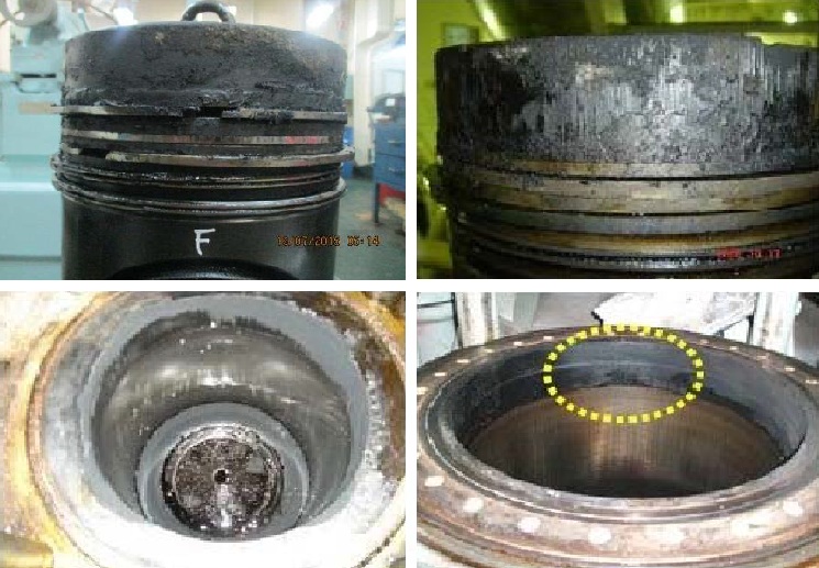
Ans: The Cylinder Liner Protection Ring Is Located At The Top Of The Liner And Its Existence Purpose Is To Protect The Liner From Thermal And Mechanical Fatigue From Combustion.

Q. Why Sometimes It Causes Problem In The Turning Of Engine?
Ans: When Engine Stopped For Long Time, Carbon Compound Which Adhered To Protection Ring And Piston Top Rand, With Absorbing Moisture, Is Swollen And The Piston Which Is In Top Position Sticks To Protection Ring, Eventually Causes Engine Turning (or Engine Starting) Impossible. So, If Engine Is ST/BY For Long Period, A Hand Turning To Be Done Every Alternate Day, While Blow Through Once Per Week.Image Text

Q. What Is The Reason Of Such Deposits On The Protection Ring?
Ans: Deposit Of Combustion Residue Due To Using Nonflammable Fuel And Low Load Operation Is The Reason, But Abrasion Of Protection Ring Which Invalidates Its Function Of Raking Out Carbon Compound Is Regarded As One Of The Reason. Using Protection Ring Which Exceeds Abrasion Limitation Might Cause Stick By Combustion Residue. In Every Maintenance, Practice Protection Ring Measurement And If It Exceeds Limitation Of Abrasion, Replace With A New One.

Q. How To Take Out A Stuck Protection Ring?
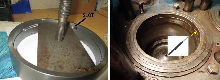
Ans: Sometimes The Protection Ring Does Not Get Easily Extracted, Due To Excessive Carbon Deposits And The Extracting Implement Gets Damaged During This Effort. In This Case, The Solution Lies In Punching The Protection Ring (at The Slots – See Photo Below) Upwards (PRIOR Using The Extracting Implement) Using A Pin Punch, Then Punch The Protection Ring Top Peripheral Surface With A Plastic Hammer And After Use The Extracting Implement.
Image Text

All you need to know about Classification societies

What Do You Mean By Classification Society?

What Do You Mean By Classification Society?
A Classification Society Is An Organisation Which Publishes Its Own Classification Rules (including Technical Requirements) In Relation To The Design, Construction And Survey Of Ships2, And Has The Capacity To (a) Apply, (b) Maintain And (c) Update Those Rules And Regulations With Its Own Resources On A Regular Basis.It Also Verifies Compliance With These Rules During Construction And Periodically During A Classed Ship's Service Life.It Is Not Controlled By, And Does Not Have Interests In, Ship-owners, Shipbuilders Or Others Engaged Commercially In The Manufacture, Equipping, Repair Or Operation Of Ships.
           Classification Society  is Authorised By A Flag Administration As Defined In SOLAS Chapter XI-1, Regulation 1 And Listed Accordingly In The IMO Database, Global Integrated Shipping Information System (GISIS).

What Is The Purpose Of Classification Society?Image Text
The Purpose Of A Classification Society Is To Provide Classification And Statutory Services And Assistance To The Maritime Industry And Regulatory Bodies As Regards Maritime Safety And Pollution Prevention, Based On The Accumulation Of Maritime Knowledge And Technology. The Objective Of Ship Classification Is To Verify The Structural Strength And Integrity Of Essential Parts Of The Ship’s Hull And Its Appendages, And The Reliability And Function Of The Propulsion And Steering Systems, Power Generation And Those Other Features And Auxiliary Systems Which Have Been Built Into The Ship In Order To Maintain Essential Services On Board. Classification Societies Aim To Achieve This Objective Through The Development And Application Of Their Own Rules And By Verifying Compliance With International And/or National Statutory Regulations On Behalf Of Flag Administrations. The Vast Majority Of Commercial Ships Are Built To And Surveyed For Compliance With The Standards Laid Down By Classification Societies. These Standards Are Issued By The Society As Published Rules. It Is An Independent, Self-regulating, Externally Audited, Body.

What Are The Scope Of Classification Societies?
Implementing The Published Rules, The Classification Process Consists Of: 
1. A Technical Review Of The Design Plans And Related Documents For A New Vessel To Verify Compliance With The Applicable Rules.

2.  Attendance At The Construction Of The Vessel In The Shipyard By A Classification Society Surveyor(s) To Verify That The Vessel Is Constructed In Accordance With The Approved Design Plans And Classification Rules.

3. Attendance By A Classification Society Surveyor(s) At The Relevant Production Facilities That Provide Key Components Such As The Steel, Engine, Generators And Castings To Verify That The Component Conforms To The Applicable Rule Requirements.

4. Attendance By A Classification Society Surveyor(s) At The Sea Trials And Other Trials Relating To The Vessel And Its Equipment Prior To Delivery To Verify Conformance With The Applicable Rule Requirements.

5. Upon Satisfactory Completion Of The Above, The Builder’s/shipowner’s Request For The Issuance Of A Class Certificate Will Be Considered By The Relevant Classification Society And, If Deemed Satisfactory, The Assignment Of Class May Be Approved And A Certificate Of Classification Issued.

6. Once In Service, The Owner Must Submit The Vessel To A Clearly Specified Programme Of Periodical Class Surveys, Carried Out Onboard The Vessel, To Verify That The Ship Continues To Meet The Relevant Rule Requirements For Continuation Of Class. 
Image Text
Assignment, Maintenance, Suspension And Withdrawal Of Class :
Class Is Assigned To A Vessel Upon The Completion Of Satisfactory Review Of The Design And Surveys During Construction Undertaken In Order To Verify Compliance With The Rules Of The Society. For Existing Vessels, Specific Procedures Apply When They Are Being Transferred From One Class Society To Another. Ships Are Subject To A Through-life Survey Regime If They Are To Be Retained In Class. These Surveys Include The Class Renewal (also Called “special Survey”), Intermediate Survey, Annual Survey, And Bottom/docking Surveys Of The Hull. They Also Include Tailshaft Survey, Boiler Survey, Machinery Surveys And, Where Applicable, Surveys Of Items Associated With The Maintenance Of Additional Class Notations. 
The Surveys Are To Be Carried Out In Accordance With The Relevant Class Requirements To Confirm That The Condition Of The Hull, Machinery, Equipment And Appliances Is In Compliance With The Applicable Rules. 
It Is The Owner's Responsibility To Properly Maintain The Ship In The Period Between Surveys. It Is The Duty Of The Owner, Or Its Representative, To Inform The Society Of Any Events Or Circumstances That May Affect The Continued Conformance Of The Ship With The Society’s Rules. 
Where The Conditions For The Maintenance Of Class Are Not Complied With, Class May Be Suspended, Withdrawn Or Revised To A Different Notation, As Deemed Appropriate By The Society When It Becomes Aware Of The Condition.

Centrifugal Pumps Vs Positive Displacement Pumps

The pumps behave very differently when considering

Centrifugal and positive displacement pumps, both used on board. Selection of these pumps basicaly depends on the behavior and ship board requirements. Centrifugal pumps are most common type of pumps on board ships. Almost all of the pumps on board for seawater or fresh water are of centrifugal type. positive displacement pumps are used for high pressure requirements, like FO supply pump, FO and LO transfer pump, sludge pump etc. Behaviour and performance of these pumps changes distinctly for any change in parameter like viscosity, presure head. Lets see how these pumps behave with the change through graphs.

Flow rate versus pressure head
By looking at the performance chart to the right you can see just how different these pumps are. The centrifugal has varying flow depending on pressure or head, whereas the Possitive Displacement pump has more or less constant flow regardless of pressure.

Flow rate versus viscosity
Another major difference between the pump types is the effect viscosity on the capacity of the pump. Centrifugal pumploses flow as the viscosity goes up but the Possitive Displacement pump’s flow actually increases. This is because the higher viscosity liquids fill the clearances of the pump, causing a higher volumetric efficiency. Remember, this chart showseffect of viscosity on the pump flow; when there is a viscosity change there is also greater lineloss in the system.

Efficiency versus pressure
The pumps behave very differently when considering mechanical efficiency.looking at the efficiency chart to the right you can see the impact of pressure changes on thpump’s efficiency. Changes in pressure have little effect on the Possitive Displacement pump but a dramatic one on the centrifugal.

Viscosity versus Efficiency  
Viscosity also plays an important role in pump mechanical efficiency. Because the centrifugal pump operates at motor speed, efficiency goes down as viscosity increases due to increased frictional losses within the pump. Efficiency often increases in a Possitive Displacement pump with increasing viscosity. Note how rapidly efficiency drops off for the centrifugal pump as viscosity increases.

Behaviour of NPSHR 
Another consideration is NPSHR. In a centrifugal the NPSHR varies as function of flow, which is determined by pressure and viscosity as discussed above. In a Possitive Displacement pump, NPSHR varies as a function of flow which is determined by speed. The lower the speed of a Possitive Displacement pump, the lower the NPSHR.

Operation of pumps at different points on curve
Another thing to keep in mind when comparing the two types of pump is that a centrifugal pump does best in the center of the curve. As you move either to the left or right, additional considerations come into play. If you move far enough to the left or right, pump life is reduced due to either shaft deflection or increased cavitation. With Possitive Displacement pump you can operate the pump on any point of the curve. In fact the volumetric efficiency as a percent actually improves at the high speed part of the curve. This is due to the fact that the volumetric efficiency is affected by slip, which is essentially constant. At low speed the percentage of slip is higher than at high speed.

Pump selection
High viscosity : Viscosity affects cosiderably the flow rate and efficiency of a centrifugal pump. While many centrifugals are cataloged to 1,000 cSt and higher, PD pumps are clearly the better choice when considering the high energy costs.

High Pressure : While some centrifugals can be run in series to boost the pressure, none can compete with PD pumps for high pressure applications. Pressure limits will depend on the design of each pump, but pressure of 250 PSI (580 feet) are not unusual for a PD pump, with some modelsgoing over 3,000 PSI (7,000 feet). The capability for a PD pump to produce pressure is so great that some type of system overpressureprotection is required.

Suction Lift : By their nature, PD pumps create a vacuum on the inlet side, making them capable of creating a suction lift. Standard ANSI centrifugals do not create a vacuum and cannot create a suction lift. There are self-priming centrifugal designs that can lift liquid an average of 15 feet when partially filled (13” hg vacuum). Many dry PD pumps can pull that or better and wetted PD pumps (a pump that is not full of liquid but with some liquid in it) can often reach vacuums of 25 to 28” hg. PD pumps are the logical choice when a suction lift is required.

Pressure Variation : The first graph above clearly illustrates the effect of changes in pressure changes the flow rate of a centrifugal pump. Additional restrictions such as debris in a filter, corroded / rough pipingor a valve left too far closed (or too far open) can have a dramatic effect on a centrifugal pump’s flow rate and efficiency. PD pumps maintain their flow rate and efficiency even with significant changes in pressure

Variation in Viscosity : Many liquids vary in viscosity depending on temperature or due to chemical reaction. A rise in viscosity will alter the flow rate and efficiency of centrifugal pumps. PD pumps become the clear choice for variable viscosity applications.

Cost : PD pumps are costly as compare to centrifugal pumps. So for cost cutting purposes centrifugal pumps comes first in choice.

High flow Rate/Capacity : Where high flow rate at low pressure is required, centrifugal pumps are better option. They can give maximum flow rate that is the reason they are used for ballast, main sea water pump, fire pump etc.

The data presented here is for specefic application. centrifugal was picked at its Best Efficiency Point (BEP) and the Possitive Displacement pump (Internal Gear) was selected to match the flow, viscosity, and pressure. Different applicationshave different curves and efficiencies. These curves are presented as an example of the performance behavior differences of the two pump principles.

Service air compressors on board ship

Service air compressor onboard is used for low pre

FUNCTION AND CONSTRUCTION
Service air compressor onboard is used for low pressure air compression (around 7bar) which is used as general purpose air( cleaning, filter cleaning, operating pneumatic hand tools and pumps, ship air horns)  and also for control air for different pneumatic control systems (blower dampers, E/R control air, air operated quick closing valve system, air for boiler burner etc.). It is the responsibility of fourth engineer to maintain  this to best of its effeciency. Screw compressors are very reliable and only timely maintanance routines such as filter and seperator change are enough to have smooth operation.
In this series we will discuss every aspect of service air compressor starting from general introduction to different case studies regarding malfunctioning of service air compressors on board ships. This series also includes FAQ regarding maintainance and construction of service air compressor.

FUNCTION: 
Air is taken in via suction air filter. The clean air, filtered of dirt and dust, is sucked into screw-end. This air is compressed at screw-end and transferred to oil separator, together with a lot of cooling oil, which has also been injected during the operation. Air and oil are separated within oil tank and oil separator. The separated air goes through minimum pressure valve and is transferred to the after cooler, which cools down the air (Please note that there is no separate oil pump in service air compressor, min pr. v/v holds the air till air pressure rises to a certain value inside the tank, after that it allows air to go through aftercooler. The compressed air inside oil tank provides required pressure to oil.)
The cooled air is then transferred to air reservoir. On the other hand, oil in separator element is transferred to oil filter and then to cooler, pushed by air pressure inside separator and finally reinjected to screw end. Here the oil is cooled by the cut in and cut out of oil/after cooler fan according to the temperature (some models also have thermostatic valve after oil tank which transfer the oil directly to air end if the oil temp is below certain temp e.g. 75°c. if temp is more thermostatic valve sent fraction of oil to oil/after cooler accordingly and finally oil is reinjected to screw end for lubrication and cooling.)
A branch is bled from oil/air tank as control air which is supplied to unloader or air control valve through separate piping.
When unloading inner pressure of oil tank, is exhaust to the atmosphere side of unloader.

DIFFERENT PARTS AND THEIR FUNCTION:
Suction filter– Its purpose is to remove dust from inlet air. It contains dry-type element to remove dust of more than about 10 µ. It is provided with maintenance indicator/ differential pressure indicator for suction filter.
Unloader-  It is mounted on air inlet of screw-end. This unloader functions to reduce load at starting and to regula
te pressure by automatically openingAnd closing inlet port during the operation and limiting the air flow. This is controlled by pressure switch and solenoid valve.

Screw-end (Compressor body)- Screw-end is composed of male rotor with n lobes and female rotor with n+1 sockets. Each rotor is supported by a roller bearing and 2 pieces of tapered roller bearing. As the rotor turns and air is sucked from upper inlet port and is compressed in the space between casing and rotors. Compression continues until the space comes to the outlet port at bottom side and the air is exhausted.

Screw-end (Compressor body)- Screw-end is composed of male rotor with n lobes and female rotor with n+1 sockets. Each rotor is supported bya roller bearing and 2 pieces of tapered roller bearing. As the rotor turns and air is sucked from upper inlet port and is compressed in the space between casing and rotors. Compression continues until the space comes to the outlet port at bottom side and the air is exhausted.

Oil separator element– The oil separator separates oil in the air discharged by screw-end. This machine has a cartridge style separator element. Air flows from the outside to the inside of separator element, and oil is separated. The oil which has been removed collects inside and is eventually reinjected into the screw-end.

Minimum pressure valveit is mounted at separator outlet. This compressor has no oil pump.
Lubricating oil pressure is so designed as to be held by air pressure inside oil tank.
Accordingly, lubrication must be performed by raising lubricating oil pressure immediately after starting. On that account, minimum pressure valve installed so that air will not be discharged until separator inner pressure is approximately 0.5MPa(5kg/cm2). It  also  functions as check valve since it is closed at unloading and stop.

Oil Filter- it filters particle larger than 5-10 µ in oil. It is of cartridge type.
 
Air and oil cooler/ After cooler-  oil and after cooler are integrated into a single piece cooler made of Aluminum. One side of which acts as a oil cooler and other half as air/after cooler. Cooling air is blown with a fan towards the cooler.
 
Thermostatic valve In order to prevent condensation of water in oil, oil flow in to oil
cooler is automatically regulated so that lubricant temperature will be kept constant.
In the case temperature is low, as bypass circuit of thermostatic valve is open, oil enter oil filter not going through oil cooler and transferred to screw end. When lubricating oil temperature rises and became 70°C, bypass circuit of thermostatic valve will close down and transferred to screw-end.

 1.  Valve position when lubricant temperature is low.  2. Valve position when lubricant temperature is high

Pressure Switch-Pressure switch is used turn capacity control solenoid valve on and off.


Points to be mentioned in a handing over note of a 4/E.

Sample copy of a handing over note for fourth engi

             SAMPLE COPY OF A HANDING OVER NOTE FOR FOURTH ENGINEER.                                                         
                                                        
                                                                          M.T. Vessel Name

                                                       FOURTH ENGINEER HANDING OVER NOTE
 
 PORT- SUEZ                                                                                                                                DATE- 01/11/2016
 

Welcome to M.T.XYZ, flag- S****, IMO no. 9*******, DW- 46791mt,
GRT-29168, built- South Korea, chemical ship type -2, main engine- MAN B&W 6S50MC-C,               


DURING UMS
If you are on duty, call to bridge at 18:00 hrs and put on UMS mode.
At 2200 to 2300hrs make safety round and inform bridge every 15 minutes during the rounds as no dead man alarm in engine room. At present E/R Kept manned
 
PUMPS
 All pumps working satisfactorily.
All maintenance jobs done according to PMS (PLANNED MAINTENANCE SCHEDULE)
During my contract period following pump overhauled:-

  1. Main cooling sea water pump no 1
  2. Main cooling sea water pump no 2
  3. Sludge pump
  4. Oily Bilge pump

                              
INCINERATOR
Incinerator is working satisfactory. But during burning garbage sluice door is malfunctioning sometime due to air cylinder seal leaking.
Burning of garbage must be recorded to GARBAGE INCINERATOR LOG for Chief Officer’s record in ECR computer. COMMON FOLDER.
Burning of sludge must be done whenever is possible/allowed. All oil transfer and burning activities should be recorded and chief engineer to be informed. Have to maintain the daily ER sounding book.
 
SEWAGE SYSTEM
Sewage and Vacuum system are in good working order.
Recently received spares and all cabin vacuum related problem solved.
Gamazyme 700FN to be added weekly in one of the toilet (STBD/PORT) side to maintain aerobic bacteria in the system..
Both vacuum pumps are in good condition.
Before arrival in port Close SEWAGE OVER BOARD VALVE and put a seal and lock. Seal number must be recorded to ER daily logbook and seal log book including date.
Sewage holding tank to be used during the port and anchorage stays
Note- sewage plant & sewage holding tank should be flushed with sea water at appropriate intervals
  
WATER MAINTENANCE TEST
Water analysis for Boilers and Cooling water should be done regularly. Water proof should be filled up every day to record the analysis. And should generate the final report at every month end. Have all files in ECR computer common folder. Called "water proof" Boiler water p –alkalinity found to be low in both boiler due to heavy exchange of feed water during tank cleaning operation.
.
CHEMICALS
Inventory of chemical is taken at the end of every month. Same report to be given to     2nd engineer for PMS update, any chemical needs must be discussed with the other engineers and requisition to be raised thereafter.
 
BOILERS
Composite boiler water washing for both economizer and fire side last carried out on 13 oct 2016 Boiler swirler, burner, flame eye routine maintenance done 13 oct 2016 Before every port arrival and departure, composite boiler nozzle, flame eye, sight glass and electrodes to be cleanedAuxiliary Boiler now operated in emergency mode
Auxiliary boiler nozzle and swirler cleaned on 28/10/2016. Aux. boiler Chemical dosing pumps is faulty not functioning already ordered new one. Waiting to receive. Careful attention to be paid for the tank level as pump should not run dry.
Blow down should be carried out regularly for both the boilers
 
COMPRESSOR
Both main air compressors running good done all routine as per PMS.
Air filter recently received not of correct size. Same noted to C/E. Topping air compressor working satisfactory sump cleaning and oil change routine done in AUG 2016. Service Air Compressor oil filter, air filter, oil separator, belt, all renewed and oil cooler cleaned (AUG 2016), as per the PMS, working good.
 
FIRE FIGHTING AND LIFE SAVING EQUIPMENT
Fourth engineer is in charge for proper maintenance of fire extinguishers/fire hoses hydrants, foam applicators and EEBD in engine room.
Monthly inspection of fire extinguishers should be done and recorded, any abnormality to be reported to chief officer.
  
SATURDAY ROUTINE
Funnel flaps to be tired out
Engine Room vent fan flaps to be tired out
Emergency air compressor to be tired out. And to maintain emergency air bottle pressure


 Incoming 4th engineer                                                                                                 Outgoing 4th engineer                                                                                                                           
                                                   
                                                                                Chief Engineer
                                                
 
                                                               BON VOYAGE AND BEST OF LUCK

FAQ MEO Orals : Safety

Frequently asked questions in MEO Orals of functio

Q. Describe camber, sheer, tumble home, Rise of floor.
Ans.
Camber:-The transverse curvature of the deck from the centerline down to the sides. This camber is used on exposed deck to drive water to the sides of the ship.
Sheer: The curvature of the deck in a fore & aft directions, rising from mid-ship to the maximum at the ends. It makes a ship more seaworthy by raising the deck at the fore & after ends further from the water and by reducing the volume of water coming on the deck.
Tumble Home: In some ships, the mid-ship side shell in the region of the upper deck is curved slightly towards the center line, thus reducing the width of the upper deck & decks above.
Rise of Floor: The bottom shell of ship is sometimes sloped up from the keel to the bilge to facilitate drainage. The rise of floor is very small.

Q. What is freeboard and reserve buoyancy?
Freeboard: It is the distance from the waterline to the top of the deck plating at the side of the deck amidships.
Reserve Buoyancy: It is the potential buoyancy of a ship and depends upon the intact, watertight volume above the waterline.
When a mass is added to the ship, or buoyancy is lost due to bilging, the reserve buoyancy is converted into buoyancy by increasing the draught. If the loss in buoyancy exceeds the reserve buoyancy the vessel will sink.

Q. Why do tankers have less freeboard?
Ans. The value of GM is greater compared to other types of ships, the openings in the tankers are small than of other ship & also the permeability is more.
      
Q. what do u mean by the stability of ship? How does stable Ship returns to the upright position if heeled by an external force?
Ans. STABILITY OF SHIP: The tendency of the ship to come back to its upright position when healed by external force is defined as the stability of the ship.
When a ship is healed, the centre of buoyancy shifts, this forms a righting lever, thus acting in the opposite direction to upright the ship.  

Q.What are tender and stiff ships?
Ans. Tender Ship: The ship with a small Metacentric height has a small righting lever at any angle & will roll easily is said to be a tender ship. In a tender ship, th

e centre of gravity lies below the transverse metacentre.
The GM is more than GZ. & these kind of ship are more stable.
Stiff Ship: The ship with a large Metacentric height has a large righting lever at any angle & has considerable resistance to rolling. A stiff ship is very uncomfortable. In a stiff ship, the Centre o

f Gravity lies above the transverse metacentre.
      

Q. What is the free surface effect? How is knowledge of free surface effect useful?
Ans. Free Surface Effect: When a tank of liquid is partially filled & the mass of liquid is moved. This movement affects the Metacentric height. This is called free surface effect.If free surface effects become more, then ship may capsize.
Q. What is the purpose of Collision bulkhead and what is it's  location?
Ans. Purpose:-
o    Avoid flooding of the ship in case of damage to bows.
Location
   o    The location is such that it is not so much forward as to get damaged on 

impact , Neither it should be too far aft so that compartment flooded forward causes extensive trim by head. As a rule located at a minimum distance to get maximum space for cargo.
   o   Minimum at 1/20 of ships length from forward perpendicular 
   o The collision bulkhead is continuous to uppermost continuous deck
   o    The collision bulkhead is 20% stronger than other bulkheads
   o    Collision bulkhead is 5 to 8 percent of ships length from forward.
 
Q. What are the types of bulkheads?
Ans.
a. Flat Bulkhead
b. Corrugated Bulkhead
c. Longitudinal Bulkhead
d. Transverse Bulkhead.
e. Watertight Bulkheadf. Non-Watertight Bulkhead
g. Fire Class A Bulkhead
h. Fire Class B Bulkhead
i. Fire Class C Bulkhead
j. Collision Bulkhead.
k. insulated bulkhead
 

Q. What are the methods of reducing rolling?
Ans. Various Methods of Reducing Rolling are:-
a. Fin stabiliser
b. Bilge keel

Q. How much length does bilge keel extends to?

Ans. It is half of the length of the ship, starting from mid-ship to fore & aft.


Q. What is an angle of loll?
Ans.
Angle of LOL: 
It is the angle at which the ship with initial negative Metacentric height will lie at rest in still water.
If the ship is further inclined to an angle more than angle of loll, the ship will sink.

Q. What is margin line?
Ans. Margin Line: 
It is the imaginary line which is drawn 75mm below the uppermost continuous deck. It denotes the limit, up to which vessel can be flooded/ loaded without sinking.

Q. What is block coefficient? If we say that block coefficient of one ship is 0.9 and the 0ther 0.95, what does it represent?
Ans. Block Coefficient:-It is the ratio of volume of displacement to the product of the length, breadth & draught.
Cb = Volume of displacement / (L x B x d)
When Block coefficient is more, it means Volume of displacement is more.

Q. What is the regulations for pumping out ER bilges in Special areas and outside special areas?

Ans. Pumping out ER Bilges outside special area:As per Marpol Annex I, Regulation 15.
Any discharge into the sea of oil or oily mixtures from ships of 400 GRT & above shall be prohibited except when all the following conditions are satisfied:-
1. The ship should be proceeding en route from Point A to point B.
2. The oily mixture is processed through an oil filtering equipment.
3. The oily content of the effluent without dilution does not exceed more than 15ppm.
4. The oily mixture does not originate from cargo pump room bilges on oil tankers.
5. The oily mixture, in case of oil tankers, is not mixed with oil cargo residues.
Pumping out ER Bilges inside special area.
1. The ship should be proceeding en route from Point A to Point B.
2. The oily mixture is processed through an Oil filtering Equipment approved by the Administration.
3. The oil content of the effluent without dilution does not exceed more than 15ppm.
4. The oily mixture does not originate from Cargo pump room bilges on oil tankers.
5. The oily mixture in the case of oil tankers, is not mixed with oil cargo residues.
6. Any discharge into the sea of oil or oily mixtures from any ship shall be prohibited in Antarctic area.
Q. Name special areas for MARPOL Annex I.
Ans. As Per MARPOL Annex 1, Regulation 1, the special areas are:-
1. Mediterranean Sea
2. Baltic sea
3. Black sea
4. Red Sea
5. Gulf area
6. Gulf of Aden area
7. Antarctic area.
8. North West European Waters
9. Oman area of the Arabian sea

5 Points all junior engineers must know before going to sea

The Most Important Thing That Will Help You Onboar

1. The Most Important Thing That Will Help You Onboard Is Your Knowledge, Hence  you Must Have Basic Knowledge Of IC Engines, Purifiers, Compressors, Refrigeration Cycle And Plant, Marine Boiler, Steering Gear, Auxilliary Machinery, Pumps, Framo (for Tankers), Basic Automation, Marine Electro Technology.

2. How Can You Acquire The  knowledge?
You Need To Read Books During Your Pre-sea Years, And Remember Just Getting Placements Is Not Enough, If You Are Not Good At Things, You Will Face A Lot Of Problems On Board. Mentioned Here Are The Books You Need Be Thorough With.
For Internal Combustion Engines:
(i)  Reeds 
(ii) D.K Sanyal
(iii) Lambs Question Answers

All Of These Books Are Good, But It Would Be Better If You Stick To One And Read It Thoroughly Before You Switch To Other, So That You Get The Grasp Of The Topics. In Case You Need Any Assistance Regarding Any Topic , Its Always Advised To Look Up To Internet Or Visit Marinelookout And Find Your Answers. 

For Marine Auxiliary Machinery:
(i) HD Mcgeorge.(it Is The Bible For This Subject)
(ii)J.K. Dhar (if You Find Difficulty With Any Topic In McGeorge)

For Marine Boilers: 
(i) GTH FLannagan(best Book Throughout Your Career)
(ii) Milton.

3. Things You Need To Learn Onboard.
Always Keep In Mind While Your Training You Are Onboard To First Learn Then Earn. Some Of The Things You Need To Learn Onboard.
(i) Pipe Line Tracing (eg.  Bilge , Sludge , Fuel Oil Transfer Line, Fuel Oil Service Line, Lub Oil Transfer Line, S.w.cooling Line, Starting Air Line, Fire Line, Bilge & Ballast Line, Ows Line)
(i) Starting And Stopping Of Every Machinery. For E.g Purifier, Compresser, Freshwater Generator, A/E Etc.
(iii) How To Take Bunker And Internal Transfers.
(iv) Sludge/ Bilge  transfer And Shore Discharge Procedores

4.You Should Be Familarised With Recordkeeping,
I) Engine Room Log Book
Ii) Garbage Record Book
Iii) Oil Record Book
Iv) 4/E And 3/E Paper Works

5. You Should Be Well Versed With Terms Like
I) Bunkering 
Ii) Sludge Transfer 
Iii) Bilge Transfer
Iv) Sounding

At Last, Follow Safety Procedures. Keep Your Mind Always Alert And Aware In The Engine Room To Avoid Any Accidents. 

​Mechanical Hydraulic Governor

The mechanical-hydraulic governor controls diesel

Q. Give a brief description for a Mechanical Hydraulic Governor?
Ans:
The mechanical-hydraulic governor controls diesel gas or dual fuel engines or steam turbines. The governor is mechanically linked to the fuel racks or to the fuel valves, depending on the system. The maximum travel of the output (terminal) shaft is 42 deg .The recommended travel of the output shall is 28° from no load to full load, which allows sufficient over travel at each end so that the governor can shut down the prime mover and also give maximum fuel when required. Normally, Mechanical Hydraulic Governor operates isochronously (constant speed) regardless of load on the engine. The recommended rated speed range for the governor drive is 1000 to 1500 rpm. The drive power requirement is 249W (1/3 hp) at normal speed and operating temperature. The governor may be driven either clockwise or counterclockwise. Operating temperature range for the governor is -29 to +99 Deg C.
Basic operation is similar for all types. The only difference is in the method of setting the speed. Auxiliary devices provide different functions but do not alter the basic operation of the governor. This schematic shows a basic design and does not include any auxiliary equipment.

Q. Give a detailed Component Description for the Mechanical Hydraulic Governor?
Component Description 

Before getting into the operation, a brief description of the components will facilitate understanding the operation.
Oil Pump
The purpose of the oil pump (14) is to provide oil pressure for the governor. The pump gets its oil from    the self-contained sump (15). The oil pump is a positive displacement gear pump with four check valves   (13) for either direction of rotation. One pump gear is part of the rotating bushing and the other is part   of the laminated drive. The rotating bushing is driven by the governor drive shaft which is driven by the   prime mover. As the bushing rotates, it rotates the laminated drive. The oil pump gears can be driven   either clockwise or counter clockwise. Oil flow is directed through the check valve 

system into the  accumulator system(11).

Accumulator
The purpose of the accumulator (11) is to store oil under pressure for the operation of the UG governor. The accumulator (two cylinders) also acts as a pressure relief valve if oil pressure increases above 827 kpa/120 psi.The accumulator (11) consists of two spring loaded pistons. Oil is pumped into the cylinders and pressure is increased as the accumulator springs are compressed. When the oil pressure exceeds 827 kPa/120 psi ,oil is released back to sump through a relief port(12) in each cylinder. 
Oil flows franc the accumulator through passages to the top of the power piston and to the pilot valve system.
Power Piston

The purpose of the power piston (9) is to rotate the governor output shaft to the increase or decrease fuel position. The power piston is a differential type with oil pressure on both sides of the piston. The top end of the power piston is connected to the governor output shaft (6) through a power lever and link assembly. The bottom of the power piston has a larger area than the top of the piston. Therefore, less oil pressure is needed on the bottom than on the top to maintain the piston stationary. If the oil pressure is the same on both the top and bottom of the piston, the piston moves up to rotate the governor output shall in the increase fuel direction. The piston moves down only when oil under the piston is released to sump. Oil to and from the bottom of the power piston is regulated by the pilot valve system.

Pilot Valve System
The purpose of the pilot valve plunger and bushing is to control the flow of oil to or from the bottom of the power piston. The pilot valve system includes the rotating bushing (38) and the pilot valve plunger (39). The bushing (38) is rotated by the drive shaft (36) .while the pilot valve plunger is held stationary Through this rotation, fiction between the pilot valve and bushing is reduced. The pilot valve plunger has a control land that regulates oil flow through ports in the bushing. When the pilot valve plunger (39) is lowered, high pressure oil flows under the power piston (9), raising it. When the pilot valve plunger is raised, oil is released to yaw from under the power piston (9), lowering it. The higher pressure on top of the power piston(9) forces the piston down When the pilot valve plunger (39) is in its centered position the control land covers the control port as shown in the schematic (Figure 3-1), and there is no movement of the power piston. The movement of the pilot valve plunger (39) is controlled by the ballhead system (23) and the dashpot compensation pistons (34) and (35).

Ball head System
The purpose of the ballhead system (23) is to sense speed changes of the pine mover as compared to the speed setting reference given by the speeder spring(25) and to position the pilot valve plunger (39).The ballhead system includes a ballhead (23), flyweights (24), a speeder spring(25), a thrust bearing (30), a speeder plug (29),and a speed setting rod (21). As the governor drive shaft (36) rotates: the gear on the laminated drive (32) turns and rotates the ballhead gears (23). The flyweights (24) are attached to the ballhead with pivot pins and a thrust bearing (30) rides on the toes of the flyweights (24). The speeder spring (25) is held in position with the thrust bearing (30) by the speeder plug (N).The speeder plug (29) is used to set a pressure on the speeder spring (25).As the ballhead (23) rotates, the flyweights (24) pivot outward due to the centrifugal force. At the same time the speeder spring (25) forces the thrust bearing (30) downward on the flyweight toes. This downward force opposes the centrifugal force of the flyweights. Increasing the drive speed increases the centrifugal force. Compressing the speeder spring (25) with the speeder plug (29) increases the downward force applied to the flyweight toes, and in turn increases the governor speed setting. The prime mover must run faster to generate a centrifugal force greater than the speeder spring force to balance the system again.Speeder spring force or speed setting (25) is controlled manually through the synchronizer (speed setting) adjusting knob (5). It can also be controlled from a remote area if the governor is equipped with a speed setting motor (1).

Compensation System
The purpose of the compensation system is to give stability to the governor and obtain steady state speed control. Also, when correctly adjusted, the compensation system effectively regulates the amount of fuel necessary to bring the engine to the required output to adjust to a decrease or increase in load. The compensation system creates a mall temporary change of speed setting with governor output shaft movement to produce a stabilizing speed droop characteristic in the governor. The change of speed setting is followed by a slow return of speed setting to its original value. Compensation is simply another word for temporary speed droop characteristic. The compensation system includes a large dashpot compensation piston (34), a dashpot compensation piston (35), a floating lever (31), a compensation adjusting lever (22) with a pivotable fulcrum (18), and a needle valve (33), See Figure 3-1. The large dashpot compensation piston (34) is connected to the governor output shalt (6) by a compensation adjusting lever (22). A pivotable fulcrum (18) rides on the compensation adjusting lever (22). Changing the fulcrum's (18) position allows the compensation lever (22) to control the amount of stroke available for the large dashpot compensation piston (34).
The small dashpot compensation piston (35) is connected through. A floating lever (31) to the pilot valve plunger (39) and the speeder-rod (21).Moving the large dashpot compensation piston (34) down forces oil under the small dashpot compensation piston (35). As the small dashpot compensation piston (35) is forced upward, it lifts the pilot valve plunger (39) to close off the control port which stops the flow of oil to the bottom of the power piston (9).The needle valve (33) is a variable orifice which controls the flow of oil between both the large (34) and the small dashpot compensation (35) pistons, and the oil sump.

NOTE: Compensation must be properly adjusted to the particular engine and load to provide stable operation (see Chapter 4, Compensation Adjustments).

Load Limit Control
A load limit control is also a standard feature on the governor. It limits the amount of fuel supplied by restricting the travel of the governor output shaft.An indicator dial shows the governor output shaft limit position. The load limit control may also be used for shutting down the prime mover by turning it to zero.  The purpose of the load limit control is to hydraulically and mechanically limit the load that can be placed on the engine by restricting the travel of the governor output shaft in. the increase fuel direction and consequently the amount of fuel supplied to the engine. The load limit control may also be used for shutting down the engine by turning it to zero.

CAUTION
Do not manually force prime mover linkage to increase fuel without first turning the load limit control knob to maximum position (10). Failure to do so may cause damage and/or failure of governor internal parts.

The load limit control consists of an indicator disc (7) geared to a load limit rack(8). The control knob is also attached to the load Limit cam (16).Load is limited mechanically by positioning the load limit knob (cam 1.6). When the load indicator reaches the preset point, the pilot valve plunger (39) is Lifted, stopping any further increase in fuel Turning the load limit control to zero to shut down the engine turns the cam (16) forcing the load limit (shutdown) lever (20) and shutdown strap (17) clown As the right end of the load limit (shutdown) lever (20) is forced downward, it pivots about its fulcrum and lifts the pilot valve plunger (39), releasing oil from under the power piston (9). Pressure oil acting on top of the power piston (9) forces it downward, rotating the governor output shaft (6) to minimum fuel and causing the prime mover to shut down.

Synchronizer
The synchronizer is the speed adjusting control and is used to change engine speed for a single unit. On engines paralleled with other units it is used to change engine load. The upper knob (called -SYNCHRONIZER- knob on most models or 'SPEED SETTING KNOB' on later models) is the control models. The lower knob ("SYN. INDICATOR') has no function of its own but has an indicator disc which shows the number of revolutions of the synchronizer (speed setting) control knob.

Speed Droop
Speed droop is incorporated in the governor to divide and balance load between units driving the same shaft of paralleled in an electrical system. Speed droop, or simply droop, is one method of creating stability in a governor. Droop is also used to divide and balance load between units driving the same shaft or paralleled in the electrical system. Droop is the decrease in speed that occurs when the governor output shaft moves from the minimum to the maximum fuel position in response to a load increase, expressed as a percentage of rated speed. If instead of a decrease in speed, an increase tales place, the governor shows a negative droop. Negative droop will cause instability in a governor. Too little droop can cause instability in the form of hunting, surging, or difficulty in response to a load change. Too much droop can result in slow governor response in picking up or dropping off a load.
Using au example where the governor speed is 1500 rpm at no load and 1450 rpm at full load.  Droop can be calculated with the formula:

     %Droop =   No load speed — full load speed   x 100   
    full load speed

     %Droop =     1500 rpm – 1450 rpm   x 100 = 3.5%
                                 1450 rpm

E the decrease in speed is greater than 50 rpm when the governor output shaft moves from the minimum to the maximum fuel position, droop greater that 3.5% is shown by the governor. If the decrease in speed is less than 50 rpm droop less than 3.5% is shown by the governor.

NOTE: If the governor output shaft does not use the full 30' of available travel from "NO LOAD' to "FULL LOAD", droop will also be reduced proportionately. Marks on the droop adjustment scale on the dial panel are reference numbers only and do not represent droop percentages. Thus the 100 mark does not represent 100% droop. It represents the maximum droop percentage available on that particular governor model.

Speed droop consists of a control knob, cam and linkage, which when preset, varies the compression of the speeder spring as the output shaft rotates. Increasing the fuel reduces speeder spring compression and, in turn, the governor speed setting. The unit gradually reduces its speed as load is applied. This relationship between load and speed acts as a resistance to load changes when the unit is interconnected with other units either mechanically or electrically.
    Reducing droop to zero allows the unit to change load without changing speed. Normally, set zero droop on units running alone. On interconnected units, set the least amount of droop possible to provide satisfactory load division.For ac generating units tied in with other units, set droop sufficiently high.
To prevent interchange of load between units. If one unit in the system has enough capacity, set its governor on zero droop and it will regulate the frequency of the prime mover system, If its capacity is not exceeded, this unit will handle all load changes. Operate the SYNCHRONIZER knob of the governor with zero droop to adjust the system's frequency. Operate the SYNCHRONIZER knob of the governors that have speed droop to distribute load between units.

Q. Describe the operation of a Mechanical Hydraulic Governor?
Operation of the Governor 

Refer to Figure with the text to better understand the operation of the governor. This schematic diagram is of a basic design and does not include any auxiliary equipment
Changes in governor speed setting produce the same governor movements as do changes in load on the engine. The description that follows is based upon speed changes caused by load changes.

Decrease in Load
When the prime mover is running on speed, the flyweights (24) are in a vertical position for normal steady state operation. The pilot valve plunger (39) is centered over the control port of the rotating bushing, and the control land stops the flow of pressure oil through the bushing (38) control port. There is no movement of the power piston (9), and no movement of the governor output shaft (6),When a decrease in load occurs and the same fuel setting is maintained speed increases. This generates the following sequence of governor movements:
1.As speed increases the centrifugal force of the flyweights (24) increases and becomes stronger than the force of the speeder spring (25).
2.The flyweights (24) tip outward and raise the speeder rod (21) and the tight end of the floating lever (31),
3. This raises the pilot valve plunger (39), opening the control port in the
rotating bushing (38). Oil is released from the bottom of the power piston
(9) to sump.
4. Pressure oil on the top side of the power piston (9) moves it downward,
rotating the governor output shaft in the decrease fuel direction.
5. Linkage from the governor output shalt (6) lowers the compensation adjusting lever (22) which rotates at the fulcrum (18), raising the large dashpot compensation piston (34).
6.Suction is thus applied to the chamber of the small dashpot compensation
piston (35), lowering the left end of the floating lever (31).
7.This lowers the pilot valve plunger (39) closing the control port (37).
8. As sump oil flows through the needle valve (33) from the sump into the
dashpot compensation piston assembly (34 and 35), the small dashpot
compensation piston (35) is returned to its normal centered position by the compensation spring at the same rate as the speeder rod (21). This keeps the pilot valve plunger (39) in its centered position
9. The control port in the rotating bushing (38) is kept closed by the land on
the pilot valve plunger (39).
10. This stops the governor output shalt and power piston movement in the new decreased fuel position. This is the position needed to run the prime mover at the selected speed setting with the new load.

Increase in Load
When an increase in load occurs and the same fuel setting is maintained, speed decreases. This generates the following sequence of governor movements:
1. As speed decreases, the centrifugal force of the flyweights (24) decreases
and the opposing speeder spring (25) force is now greater than the centrifugal force of the flyweights (24).
2. The flyweights (24) tip inward and lower the speeder rod (21) and the right
end of the floating lever (31).
 3. This lowers the pilot valve plunger (39), opening the control port in the
rotating bushing (38). Pressure oil is released through the control port into the lower cylinder of the power piston (9).
 4. The power piston is forced upward by the pressure oil acting on the larger lower surface area of          the power piston rind the governor output shaft is rotated in the increase fuel direction.
5. Linkage from the governor output shaft (6) lifts the compensating adjusting
lever (22), which rotates at the fulcrum(18), lowering the large dashpot compensation piston (34).
 6. Pressure oil is applied to the bottom side of the small dashpot compensation
piston (35), raising the left end of the floating lever (31).
7.This raises the pilot valve plunger (39) closing the control port (37).
8. As pressure oil flows through the needle valve (33) from the dashpot compensation piston     assembly (34 and 35), the small dashpot compensation piston (35) is returned to its normal centered    position by the compensation spring, at the same rate as the speeder rod (21). This keeps the pilot    valve plunger (39) in its centered position.
9. The control port in the rotating bushing (38) is kept closed by the land on the pilot valve plunger (39).
10. This stops the governor output shaft and power piston movement in the new increased fuel position. This is the position needed to run the prime mover at the selected speed setting with the new load.
  
In both cases, a decrease or increase in load, the compensation system operates in opposite     directions. The compensation or amount of movement of the large dashpot compensation piston    (34) is controlled by the compensation adjustment that is, the position of the fulcrum (18).

The rate at which the small dashpot compensation piston (35) is returned to
normal is controlled by the needle valve adjustment, that is, the rate of flow of oil through the needle valve (33).