Normally Four Types Of Portable Extinguishers Are
Normally Four Types Of Portable Extinguishers Are Used On Board For Extinguishing A Fire:
1. Foam Extinguishers
2. CO2 Extingishers
3. Dry Chemical Powder (DCP) Extinguishers
4. Water Extinguishers
Q1. Explain The Procedure To Use Foam Extinguishers ?
Foam Extinguishers Are Particularly Useful For Extinguishing Fires Of Class 'B' Type Involving Inflammable Liquids.Foam Extinguishers Are Available In Two Types –
Mechanical Foam Extinguisher
I) It Has A Plastic Bag Filled With Foam Concentrate Over A Gas Cartridge.
Ii) The Outer Container Contains Water.
Iii) When The Seal Is Pierced By Striking The Knob, The CO2 Is Released Thereby Rupturing The Plastic Bag.
Iv) The Water And The Foam Concentrate Are Mixed And The Foam Solution Is Driven By The Pressure Of Gas Up The Tube Into The Nozzle Where It Is Aerated Into Air Foam.
V) This Extinguisher Can Be Charged On Board. Separate Foam Concentrate Packets And Gas Cartridges Are Available Along With Instructions On How To Recharge The extinguisher. Ensure Foam Concentrates And Gas Cartridges Used Are Meant For That Size Of The Extinguisher.
Chemical Foam Extinguisher
I) This Type Contains Two Containers – One The Outer Container And The Other The Inner Container.
Ii) The Inner Container Has A Solution Of Aluminium Sulphate.
Iii) The Outer Container Has A Solution Of Sodium Bicarbonate.
Iv) The Extinguisher Is Always Placed In An Upright Position.
V) To Prevent Any Accidental Mixing Of The Liquids In The Container, A Knob Is Attached To Sealing Lead Weight Which Is Kept Locked There By Closing The Opening Of The inner Container.
Vi) When The Extinguisher Is To Be Used, The Knob Is Turned To Open Position And the Extinguisher Is Turned Upside Down Permitting Both The Solutions To Mix.
Vii) A Chemical Reaction Is Set Up Which Produces Foam And Carbon Dioxide Gas. The Chemical Foam Is Released Through The Nozzle Provided.
This Extinguisher Can Be Charged On Board As Follows :
I) After The Extinguisher Has Been Discharged, Open The Extinguisher From The Top Knob, Clean Both The Inner And The Outer Containers With Fresh Water.
Ii) The Charge For The Extinguishers Comes In Packets Containing Aluminium Sulphate And Sodium Bicarbonate Powders Clearly Marked "A" And "B". Each Charge Has Both the Packets Needed For The Extinguisher.
Iii) A Note Giving Instructions On How To Fill Is Also Enclosed.
Iv) Fill Water In The Outer Container Till The Mark Provided In The Body Of The Extinguisher. Empty The Measured Water Into A Clean Bucket. Empty The Packet containing Sodium Bicarbonate Into That Bucket Of Water And Stir It Well Till All The Powder Has Dissolved. Fill The Sodium Bicarbonate Solution Into The Outer container.
V) Similarly Measure The Water Required For The Inner Container, Dissolve The Aluminium Sulphate Powder And Fill The Inner Container With The Solution.
Vi) Place The Inner Container Inside The Extinguisher Body Taking Care That Both The Solutions Do Not Mix.
Vii) Screw In The Cap Having The Lead Sealing Weight And The Knob Should Be Turned To Close Position.
Viii) Now The Extinguisher Is Ready For Use. The Extinguisher Should Be Kept Vertical And Should Be Placed In The Stand Provided For The Same.
Q2. What Are The Advantages Of Mechanical Foam Extinguishers Over Chemical Foam Extinguishers ?
Some Of The Advantages Of Mechanical Foam Extinguishers Over Chemical Foam Extinguishers
I) Mechanical Foam Extinguishers Can Be Operated Keeping The Extinguisher Upright Whereas Chemical Foam Extinguishers Have To Be Operated Keeping The Extinguisher inverted.
Ii) Since There Is No Chemical Reaction Taking Place In Mechanical Foam Extinguishers, They Are More Reliable And There Is No Delay Waiting For The Chemical Reaction to Build Up Pressure. The Foam Comes Out Instantly.
Iii) They Are Easier To Recharge.
Note:
1. Foam Extinguishers Should Not Be Used On Electrical Fires.
2.When Using On Oil Fires, The Nozzle Should Not Be Directed Into The Fire As This Will Cause The Fire To Spread. The Nozzle Should Be Directed On To A Bulkhead Above the Burning Surface To Permit The Foam To Build Up A Blanket Which Will Flow Over The Burning Liquid And Extinguish The Fire By Smothering.
Q3 What Check & Maintenance Is To Be Carried Out In Foam Type Fire Extinguishers?
I) At Least Once A Week, Clean The Exterior Body, Check Nozzle Outlet And Vent Holes And Ensure That The Plunger Is Clean And Fully Extended.
Ii) Every Quarter – Check The Internals, Gas Cartridge In Case Of Mechanical Foam, And Stir The Solutions In Both The Containers. Ensure That There Are No Sediments.
Iii) Operate The Extinguisher Once Every Year At Fixed Shorter Intervals And Monitor Its Performance. It Should Project The Foam To A Distance Of 6m For A Period Of 30 Seconds.
Iv) Pressure Test The Extinguisher Every 2 Years To Manufacturer's Stated Pressure (usually 17.5 Kgf/cm2 For 2.5 Minutes).
Q4. Explain The Procedure To Use Portable CO2 Fire Extingushers.?
I) Most Suitable For Fires Involving Electrical Appliances And Inflammable Liquid And In Places Where Foam, Water Or Dry Chemical Powder Can Damage The Equipment.
Ii) Carbon Dioxide Is Kept In Liquid Form At 50 Bars Pressure At About 15ºC.
Iii) The Top Of The Extinguisher Incorporates A Piercing Mechanism To Pierce The Seal When The Extinguisher Has To Be Used.
Iv) At The Outlet There Is A Flexible High-pressure Hose Attached To A Handle And A Discharging Horn.
A Control Valve Controls The Discharge Of The CO2. This Is Locked In Position By Means Of A Safety Pin Which Is Removed Prior To Using The Extinguisher
V) When Handling The CO2 Extinguisher Care Must Be Taken To Hold The Hose Only At The Insulated Handle Provided For That Purpose. In Case You Hold The Extinguisher At the Hose Or At The Discharging Horn, You Will Get Cold Burns As The Liquid Carbon Dioxide Expands To Gaseous State.
Vi) Similarly The Gas Should Not Be Directed On The Exposed Parts Of The Body As An Intense Cold Is Generated While The Gas Is Discharged.
Vii)Wear Proper Hand Gloves And Personal Clothing Like Full Sleeve Boiler Suit, Prior To Using The Extinguisher.
Viii) The Fire Is Extinguished By Sweeping The Discharge Horn Across The Surface Of The Burning Material.
Ix) The Fire Is Extinguished By Virtue Of CO2 Occupying The Air Space Thus Excluding Oxygen. This Condition Starves The Fire And As CO2 Being Heavier Than Air Settles down Displacing The Air.
Q5. What Are The Main Drawbacks Of CO2 Type Extinguishers?
Some Drawbacks Of The Extinguisher
I) Though CO2 Is Non-toxic,but it Can Suffocate A Person Near By And Being Heavier Than Air Will Settle Down.
Ii) If The Extinguisher Is Not Used Correctly It Could Cause Cold Burns.
Iii) Carbon Dioxide Issues Out A Dense Vapour, Which In Confined Spaces Would Impair Visibility.
Iv) The Sealing Disc Orifice May Freeze After The Initial Start There By Hindering The Flow Of Gas To The Discharging Horn. In Such A Case Shut The Valve Or Release the Lever And Start Up Again.
V)This Extinguisher Cannot Be Recharged As Easily As The Foam Type On Board And Is Usually Recharged Ashore.
Q6. What Care & Maintence Is To Be Done In Co2 Type Extinguishers?
Care And Maintenance Co2 Type Extinguishers
I) Check That The Nozzle Outlet Is Free.
Ii) Ensure That The Safety Pin Is In Place And Secured And The Release Lever Is Not Depressed.
Iii) Weigh The Extinguisher At Least Once Every Month And If There Is A Reduction Of 10% Or More In Weight Then The Extinguisher Is To Be Recharged.
Iv) The Extinguisher Is To Be Pressure Tested Before Every Recharge.
Q7. Explain The Procedure To Use DCP Fire Extinguishers?
These Type Of Extinguishers (usually Known As DCP Extinguishers) Are Suitable For Fighting Class B Fires Involving Inflammable Liquids And For Electrical Fires.
I)They Are Also Suitable For Class C And Class D Fires And To A Lesser Extent On Small Class A Fires.
Ii) They Are Unsuited For Deep Seated Class A Fires As They Do Not Have The Cooling Effect.
Iii) The Dry Chemical Powder Used In These Extinguishers Comes In Varying Combinations Depending On The Purpose Of The Extinguisher For E.g.
For Class A Fires – The Powder Is Usually Ammonium Phosphate Based.
For Class B Fires – The Powder Has A Potassium Bicarbonate Base
For Class D Fires – The Powder Is A Combination Of Sodium Potassium And Barium Chlorides
Iv) This Extinguisher Is Used Mainly For Class B Fires. The Base Is Usually Potassium Bicarbonate. The Extinguisher Is Clearly Marked As To Which Class Of Fire It Is suitable For.
V) The Powder Interfering With The Chemical Chain Reactions Occurring In The Flames Extinguishes The Fire. The Bicarbonate Decomposes Into Water And Carbon Dioxide. This Decomposition Forms A Catalytically Active Surface, Which Destroys The Free Radicals Propagating The Flame Reactions.
Vi) The Extinguisher Body Contains A Receptacle Holding The Powder.
Vii) Attached To Cap Of The Extinguisher Top Is A Carbon Dioxide Cartridge, Which Is Screwed Into It And Has An Attached Piercing Mechanism. Accidental Piercing Of The CO2 Cartridge Is Prevented By Means Of A Safety Pin, Which Should Only Be Removed When The Extinguisher Needs To Be Discharged
There Are Some Types Of DCP Extinguishers, Which Do Not Have A CO2 Cartridge, Instead The Extinguisher Receptacle Itself Is Pressurised Using CO2. This Is Usually done Ashore And There Is A Pressure Gauge On The Extinguisher Where The Bottle Pressure Can Be Read Off. The Charging Should Be Done As Per The Manufacturer's instructions.
Method Of Operation
I) Carry The Extinguisher To The Place Of Use.
Ii) Remove The Safety Pin And Strike The Knob Provided To Pierce The CO2 Gas Cartridge.
Iii) Direct The Stream Of Powder To The Base Of The Fire.
Iv)Progress Forward Moving The Nozzle Rapidly With A Side-to-side Sweeping Motion.
V) On Outdoor Locations Operate Extinguisher From Upwind Side Of Fire To Extend Effective Range Of Spray.
Q8. What Care & Maintenance Is To Be Done For DCP Type Extinguishers ?
Care And Maintenance
I) Check That The Nozzle And The Vent Holes Are Clear On A Weekly Basis.
Ii) Check That The Plunger Is Clean And Fully Extended.
Iii) Every 3 Months Check The Following :
a)Weigh The CO2 Cartridge If Fitted And Replace It If It Is 90% Or Less Than Its Original Weight.
b)The Piercing Mechanism Should Be Free.
c)he Dry Chemical Powder Should Be Free Of Caking And Granulation.
Iv) Discharge The Extinguisher At Least Once A Year To Check Its Performance. Extinguishers Can Be Discharged On A Rotation Basis.
V) If Unable To Discharge In Rotation, All Extinguishers Must Be Recharged After Every Two Years.
All DCP Extinguishers Should Be Sent Ashore To Be Pressure Tested Hydraulically Once In 3 Years.
Q9. Explain The Procedure To Use Patable Water Extinguishers ?
I) Water Extinguishers Are Most Suitable For Class "A" Fires I.e. Carbonaceous Fires In Accommodation Involving Wood, Paper And Furnishings. In These Fires, The primary Purpose Is To Reduce The Temperature Of The Burning Material.Water Is Unsuitable For Fires Involving Burning Liquids Or Gases And Live Electrical Circuits.
Ii) Water Is The Extinguishing Media In These Extinguishers, Which Is Released In The Form Of A Jet By Means Of Gas Pressure In The Upper Part Of The Container.
Iii) The Gas Pressure Is Induced Either By Mechanical Means Or By Chemical Reaction.
Iv) In Water Type Extinguishers Where Gas Is Induced By Mechanical Means (commonly Called Water / CO2 Or The Universal Type) :
V) Water Is Stored In The Extinguisher Container And A CO2 Cartridge Is Attached To The Top Assembly.
Vi) When The Cartridge Is Pierced Open By Means Of The Plunger, CO2 Under Pressure Is Released.
Vii) This Increase In Pressure Causes The Water To Be Propelled Out With Pressure.
The Properties Of Water As A Fire-extinguishing Agent are :
Q10. What Are The Advantages And Disadvantages Of Using Water For Fire Fighting?
Advantages
I) Water Is An Excellent Cooling Agent And Is Available In Large Quantities In The Form Of Sea Water.
Ii) It Absorbs More Heat For A Given Increase Of Temperature Than The Same Mass Of Almost Any Other Substance (It Has A High Thermal Capacity).
Iii) When Water Is Applied To Fire, It Is Converted Into Steam. For This Steam To Form, A Great Deal Of Heat Is Extracted From The Fire, Assisting The Cooling process.
Iv) If Water At Near Freezing Temperature Is Used In Fire Fighting, Over Five Times As Much Heat Is Extracted In Converting The Water Into Steam Than Is Absorbed In the Process Of Raising The Temperature Of The Water From Freezing Point To Boiling Point.The Smothering Effect Of Steam Produced At The Seat Of Fire Assists In The Extinguishing Process
Disadvantages
I) Water In Copious Quantities May Have An Adverse Effect On The Ship's Stability.
Ii) When Used On Burning Oil, The Water Spray May Tend To Sink Under The Oil Thereby Causing The Fire To Erupt.
Iii)It Reacts Dangerously With Class D Substances. Possibility Of Electric Shock If Used In A Straight Stream. Also Reacts With Substances Such As Acids And carbides.
Iv) Sea Water Cannot Be Used On Electrical Fires As It Is A Good Conductor Of Electricity.
V)Water May Damage Electrical Equipment, Cargo Etc As It Soaks Them And May Make Them Beyond Use.
Q11. What Are The Check & Maintenance Involved In Water Type Extinguishers?
Care And Maintenance
I) On A Regular Basis (preferably Once A Week Or Fortnight) Check Nozzle Outlet And Vent Holes On Threaded Portion.
Ii) Check Whether The Plunger Is Fully Extended And Whether The Safety Pin Is In Place.
Iii) Every Three Months Dismantle The Cover Components, Check For Damage, Clean And Grease Them As Required (avoid Over Greasing), Stir The Solution In The Body (in case Of Chemical Reaction Type), Top Up The Water Quantity To Required Level.
Iv) Ensure That The CO2 Cartridge And Gas Phial Is Intact.
V) At Least Once A Year, Operate The Extinguisher To Ensure It Functions Properly. It Must Produce A Jet Length Of 6 Mtrs For At Least 60 Seconds.
Vi) Pressure Test The Extinguisher Every Five Years As Per Manufacturer's Instructions (usually Done To 17.5 Kgf/cm2).
Q12. Explain The Procedure To Use Patable Water Extinguishers ?
The "Soda / Acid" Type Extinguisher Are No Longer In Use. The Information Has Been Provided Here Only As A Matter Of Interest.
I) In The Water Type Extinguisher Where The Gas Is Induced By A Chemical Reaction (this Type Is Commonly Known As The Soda/Acid Type):
Ii) The Container Of The Extinguisher Is Filled With Sodium Bicarbonate Solution (NaHCO3).
Iii) Near The Cap Of The Extinguisher Is A Glass Phial Containing Sulphuric Acid.
Iv) The Plunger Pierces The Glass Phial And The Sulphuric Acid Is Made To React Chemically With The Sodium Bicarbonate Solution.
V) The Reaction Produces Carbon Dioxide, Which Pressurises The Liquid Out Of The Extinguisher.
Vi) The Reaction Between Sulphuric Acid And Sodium Bicarbonate Is As Follows :
H2SO4 + 2 NaHCO3 = Na2SO4 + 2 H2O + 2 CO2
(Sulphuric Acid + Sodium Bicarbonate) = (Sodium Sulphate + Water + Carbon-dioxide )
Vii) The Water Thus Formed In The Above Chemical Reaction Is The Actual Extinguishing Agent Where As The Carbon Dioxide Acts As The Propelling Agent.
Viii) Both Type Of Extinguishers Are Normally Operated In The Upright Position By Striking The Knob To Either Pierce The Acid Bottle Or The Carbon Dioxide Seal, But there Are Some Soda / Acid Type Extinguishers Which Are Operated Upside Down.
Ix) The Gas Cartridge Type Is More Efficient And Is More Easily Recharged.
Method Of Operation
I) Ascertain Whether The Extinguisher Is The Upright Type Or The Turn Over Type.
Ii) Remove The Safety Pin And The Guard Cap And Strike The Plunger Piercing The Seal Or The Acid Phial.
Iii) Direct The Jet Emerging From The Nozzle To The Base Of The Fire, Keeping It Directed There Till The Extinguisher Is Completely Discharged.


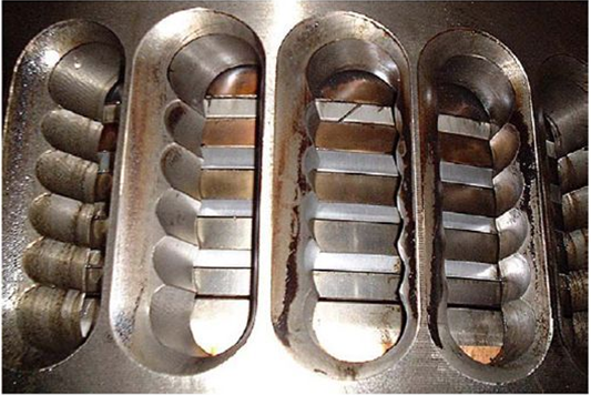
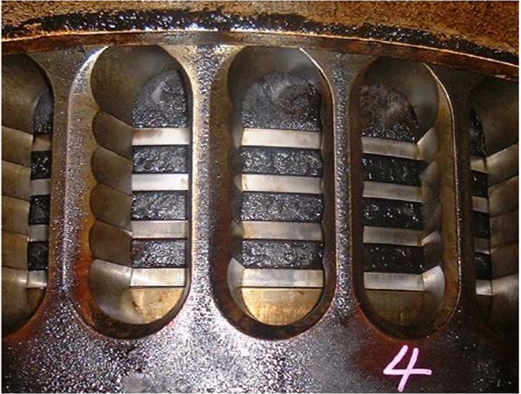
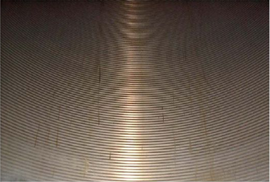 1. BEST CONDITION: Machining mark remains completely.
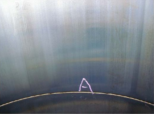 2.ORDINARY CONDITION: Machining mark has been disappeared/ Liner surface smooth & well lubricated.
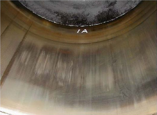 3. BAD CONDITIION: Dark patches on liner/ Scoring marks visible/ Liner surface dry.
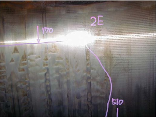 4. SULPHURIC ACID CORROSION: Low temperature corrosion.
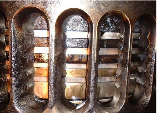
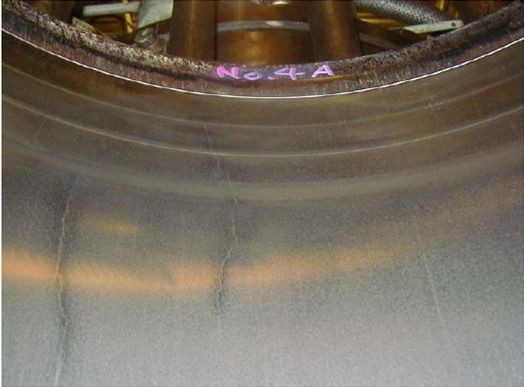 5. STEP WEAR & CRACK: There is step wears at position of TDC, also vertical crack can be seen.
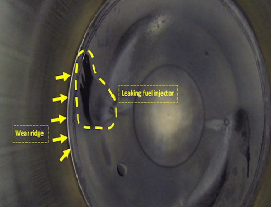 6. Fuel injector leaking/faulty
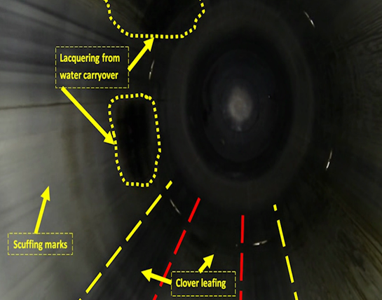 7. Clover leafing of cylinder liner
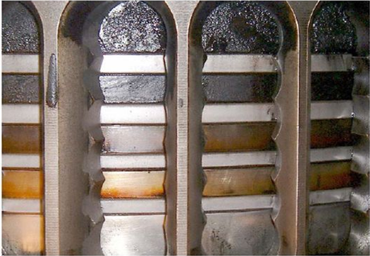
 4. WORSE CONDITION: Exhaust gas is sealed at # 4 ring.
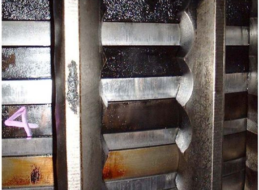 5. PISTON RING SCUFFING: Scuffing can be seen at all piston rings/ Micro seizures can be seen on ring surface/ Edges of rings are shart due to wear.


